METER / GAUGE SYSTEM, Diagnostic DTC:B1500

| DTC Code | DTC Name |
|---|---|
| B1500 | Fuel Sender Open Detected |
DESCRIPTION
This DTC is output when the combination meter assembly detects a fuel sender gauge malfunction via the direct line.
| DTC No. | DTC Detection Condition | Trouble Area |
|---|---|---|
| B1500 | When either of the following conditions is detected:
|
|
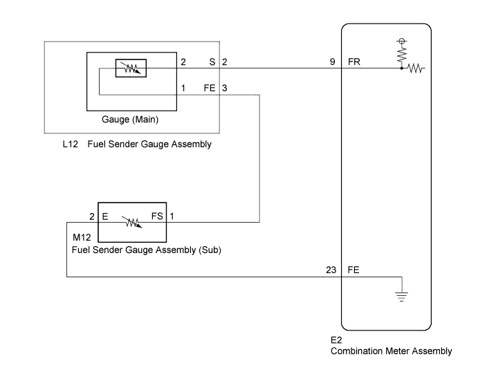
WIRING DIAGRAM
INSPECTION PROCEDURE
PROCEDURE
-
READ VALUE USING GTS (FUEL INPUT)
-
Connect the GTS to the DLC3.
-
Turn the ignition switch to ON.
-
Turn the GTS on.
-
Enter following menus: Body Electrical / Combination Meter / Data List.
-
Check the values by referring to the table below.
Combination Meter Tester Display Measurement Item/Range Normal Condition Diagnostic Note Fuel Input Fuel input signal/Min.: 0, Max.: 127.5 The current fuel level displayed Unit: Liter Result Result Proceed to Fuel level data can be displayed on the GTS and DTC B1500 is output. A Fuel level data cannot be displayed on the GTS. B
B 
INSPECT COMBINATION METER ASSEMBLY Click here
A 
REPLACE COMBINATION METER ASSEMBLY Click here
-
-
INSPECT COMBINATION METER ASSEMBLY
-
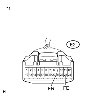
Text in Illustration *1 Front view of wire harness connector
(to Combination Meter Assembly)
Disconnect the E2 connector.
-
Measure the resistance according to the value(s) in the table below.
Standard Resistance Tester Connection Condition Specified Condition E2-9 (FR) - E2-23 (FE) Always 13.0 to 414.5 Ω
NG
CHECK HARNESS AND CONNECTOR (COMBINATION METER ASSEMBLY - FUEL SENDER GAUGE ASSEMBLY) Click here
OK
REPLACE COMBINATION METER ASSEMBLY Click here
-
-
CHECK HARNESS AND CONNECTOR (COMBINATION METER ASSEMBLY - FUEL SENDER GAUGE ASSEMBLY)
-
Disconnect the L12 connector.
-
Measure the resistance according to the value(s) in the table below.
Standard Resistance Tester Connection Condition Specified Condition E2-9 (FR) - L12-2 (S) Always Below 1 Ω E2-9 (FR) - Body ground Always 10 kΩ or higher E2-23 (FE) - M12-2 (E) Always Below 1 Ω E2-23 (FE) - Body ground Always 10 kΩ or higher L12-3 (FE) - M12-1 (FS) Always Below 1 Ω M12-1 (FS) - Body ground Always 10 kΩ or higher
NG 
REPAIR OR REPLACE HARNESS OR CONNECTOR
OK 
-
-
INSPECT FUEL SENDER GAUGE ASSEMBLY
-
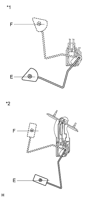
Text in Illustration *1 Front view of wire harness connector
(to Fuel Sender Gauge Assembly (Main))
*2 Front view of wire harness connector
(to Fuel Sender Gauge Assembly (Sub))
Remove the fuel sender gauge assembly Click here.
-
Check that the float moves smoothly between E and F.
-
Measure the resistance according to the value(s) in the table below.
Standard Resistance (Main) Tester Connection Condition Specified Condition 1 - 2 Float level is F (upper) 6.5 to 8.5 Ω 1 - 2 Float level is between F (upper) and E (lower) 6.5 to 187.2 Ω (Gradually changes) 1 - 2 Float level is E (lower) 183.2 to 187.2 Ω Standard Resistance (Sub) Tester Connection Condition Specified Condition 1 - 2 Float level is F (upper) 6.5 to 8.5 Ω 1 - 2 Float level is between F (upper) and E (lower) 6.5 to 227.3 Ω (Gradually changes) 1 - 2 Float level is E (lower) 222.3 to 227.3 Ω
NG
REPLACE FUEL SENDER GAGE ASSEMBLY Click here
OK
-
-
CHECK FUEL SENDER GAUGE ASSEMBLY
-
Visually check for deformation on the fuel sender gauge assembly connector.
OK There is no deformation.
NG
REPLACE FUEL SENDER GAGE ASSEMBLY Click here
OK
REPLACE COMBINATION METER ASSEMBLY Click here
-