ENTRY LOCK AND UNLOCK SWITCH INSTALLATION

-
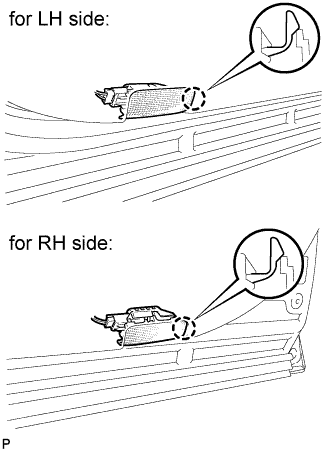
INSTALL FRONT DOOR OUTSIDE HANDLE ASSEMBLY
-
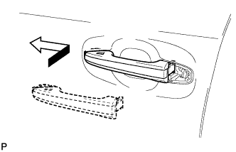
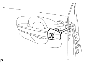
Insert the front end of the front door outside handle assembly into the front door outside handle frame.
-
Insert the rear end of the front door outside handle assembly into the front door outside handle frame, then slide the front door outside handle assembly toward the front of the vehicle to install it.
-
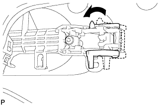
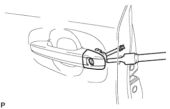
Move the lever back in the direction indicated by the arrow in the illustration to lock the door outside handle assembly.
-
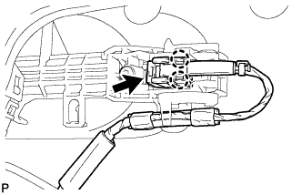
Connect the connector.
-
Engage the 2 claws.
-
-
INSTALL FRONT DOOR OUTSIDE HANDLE COVER (for Front Passenger Side)
-
Using a T30 "TORX" socket wrench, install the front door outside handle cover with the screw.
- Torque:
- 4.0 N*m { 41 kgf*cm, 35 in.*lbf }
-
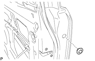
Install the hole plug.
-
-
INSTALL FRONT DOOR OUTSIDE HANDLE COVER WITH LOCK CYLINDER ASSEMBLY (for Driver Side)
-
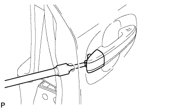
Install the front door outside handle cover with lock cylinder assembly.
Tech Tips
Make sure that the front door lock cylinder rod is inserted into the front door lock assembly.
-
Using a T30 "TORX" socket wrench, install the front door lock cylinder with the screw.
- Torque:
- 4.0 N*m { 41 kgf*cm, 35 in.*lbf }
-
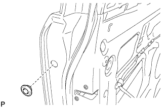
Install the hole plug.
-
-
INSTALL FRONT DOOR GLASS SUB-ASSEMBLY
-
Connect the cable to the negative (-) battery terminal.
-
Connect the power window regulator master switch assembly and move the front door glass sub-assembly so that the door glass bolts can be seen.
-
Disconnect the cable from the negative (-) battery terminal and power window regulator master switch assembly.
-
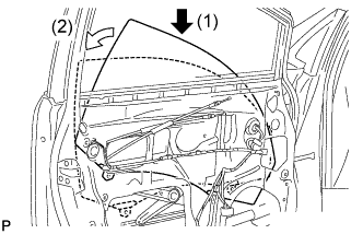
Insert the front door glass sub-assembly into the front door panel along the front door glass run as indicated by the arrows, in the order shown in the illustration.
-
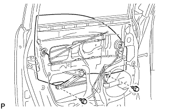
Install the front door glass sub-assembly with the 2 bolts.
- Torque:
- 8.0 N*m { 82 kgf*cm, 71 in.*lbf }
-
-
INSTALL FRONT DOOR SERVICE HOLE COVER
-
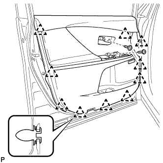
Apply butyl tape to the front door panel.
-
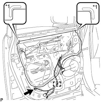
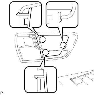
Text in Illustration *1 Reference Point Pass the front door lock remote control cable assembly and front door inside locking cable assembly through a new front door service hole cover.
-
Attach the front door service hole cover according to the reference points on the front door panel.
Note
Securely install the front door service hole cover preventing wrinkles and air bubbles.
-
Engage the clamp.
-
Install the bolt.
- Torque:
- 8.0 N*m { 82 kgf*cm, 71 in.*lbf }
-
-
INSTALL DOOR SIDE AIRBAG SENSOR
-
Check that the ignition switch is off.
-
Check that the cable is disconnected from the negative (-) battery terminal.
CAUTION:
Wait at least 90 seconds after disconnecting the cable from the negative (-) battery terminal to disable the SRS system.
-
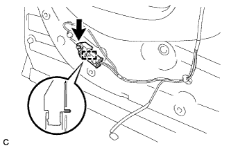
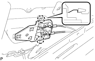
Insert the pin (stopper) into the door hole and install the door side airbag sensor to the vehicle with the bolt.
- Torque:
- 9.0 N*m { 92 kgf*cm, 80 in.*lbf }
Note
-
If the door side airbag sensor has been dropped, or there are any cracks, dents or other defects in the case or connector, replace it with a new one.
-
When installing the door side airbag sensor, be careful that the SRS wiring does not interfere with or is not pinched between other parts.
-
Make sure that the pin (stopper) is securely inserted into the door hole.
-
Tighten the bolt while holding the door side airbag sensor because the door side airbag sensor pin (stopper) is easily damaged.
-
Connect the connector to the door side airbag sensor.
Note
When connecting the airbag connector, take care not to damage the airbag wire harness.
-
Before connecting the connector, check that the position of the white housing lock is correct as shown in the illustration.
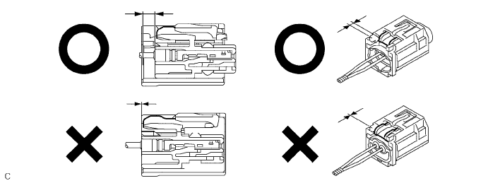
-
Be sure to engage the connectors until they are locked (When locking, make sure that a click sound can be heard).
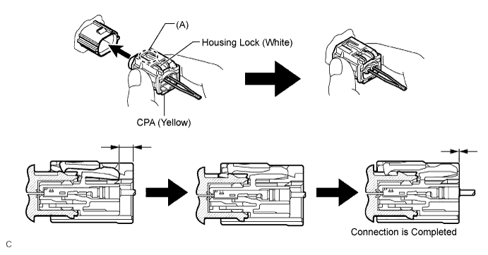
Tech Tips
When engaged, the white housing lock will slide. Be sure not to hold the white housing lock and part (A), as it may result in an insecure fit.
-
-
Check that there is no looseness in the installation parts of the door side airbag sensor.
-
-
INSTALL FRONT DOOR INSIDE HANDLE SUB-ASSEMBLY
-
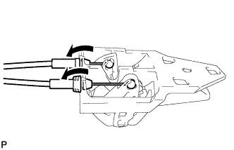
Connect the front door lock remote control cable assembly and front door inside locking cable assembly to the front door inside handle.
-
Engage the 2 claws and install the front door inside handle sub-assembly to the rear door trim board sub-assembly.
-
-
INSTALL FRONT DOOR TRIM BOARD SUB-ASSEMBLY
-
Engage the 10 clips and install the front door trim board sub-assembly.
-
Install the 2 screws.
-
-
INSTALL COURTESY LIGHT ASSEMBLY
-
Connect the connector.
-
Engage the claw to install the courtesy light assembly.
-
-
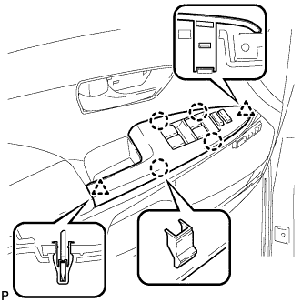
INSTALL POWER WINDOW REGULATOR MASTER SWITCH ASSEMBLY WITH FRONT DOOR ARMREST BASE PANEL (for Driver Side)
-
Connect the connector.
-
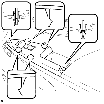
Engage the 2 clips and 4 claws, and install the power window regulator master switch assembly with front door armrest base panel.
-
-
INSTALL POWER WINDOW REGULATOR SWITCH ASSEMBLY WITH FRONT DOOR ARMREST BASE PANEL (for Front Passenger Side)
-
Connect the connector.
-
Engage the 2 clips and 4 claws, and install the power window regulator switch assembly with front door armrest base panel.
-
-
INSTALL FRONT DOOR INSIDE HANDLE BEZEL PLUG
-
Engage the 3 claws and install the front door inside handle bezel plug.
-
-
CONNECT CABLE TO NEGATIVE BATTERY TERMINAL
Note
When disconnecting the cable, some systems need to be initialized after the cable is reconnected Click here.
-
INITIALIZE POWER WINDOW CONTROL SYSTEM
-
INSPECT SRS WARNING LIGHT