LIGHTING SYSTEM Door Unlock Detection Switch Circuit
DESCRIPTION
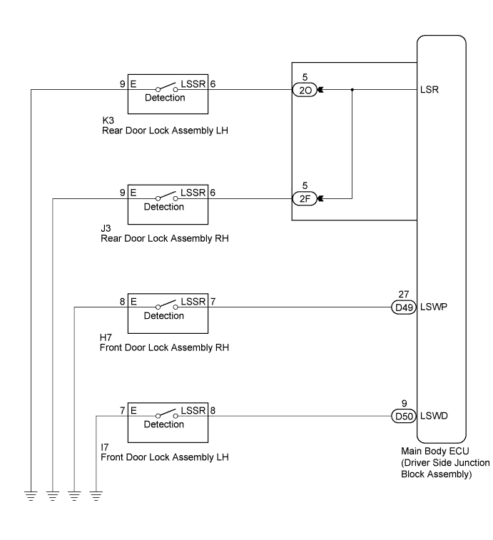
The main body ECU (driver side junction block assembly) detects the condition of the door unlock detection switch.
WIRING DIAGRAM
INSPECTION PROCEDURE
PROCEDURE
-
READ VALUE USING GTS
-
Connect the GTS to the DLC3.
-
Turn the ignition switch to ON.
-
Turn the GTS on.
-
Enter the following menus: Body Electrical / Main Body / Data List.
-
Read the display on the GTS.
Main Body Tester Display Measurement Item/Range Normal Condition Diagnostic Note FR Door Lock Pos Driver side door unlock detection switch signal/ON or OFF ON: Driver side door unlocked
OFF: Driver side door locked
- FL Door Lock Pos Front passenger side door unlock detection switch signal/ON or OFF ON: Front passenger side door unlocked
OFF: Front passenger side locked
- RR Door Lock Pos SW Rear door RH unlock detection switch signal/ON or OFF ON: Rear door RH unlocked
OFF: Rear door RH locked
When checking this item, make sure to check it with the rear door LH locked. RL Door Lock Pos SW Rear door LH unlock detection switch signal/ON or OFF ON: Rear door LH unlocked
OFF: Rear door LH locked
When checking this item, make sure to check it with the rear door RH locked. Result Result Proceed to OK A Driver side door unlock detection switch does not operate B Front passenger side door unlock detection switch does not operate C Rear door unlock detection switch LH does not operate D Rear door unlock detection switch RH does not operate E
B 
INSPECT FRONT DOOR LOCK ASSEMBLY LH Click here
C
INSPECT FRONT DOOR LOCK ASSEMBLY RH Click here
D
INSPECT REAR DOOR LOCK ASSEMBLY LH Click here
E
INSPECT REAR DOOR LOCK ASSEMBLY RH Click here
A 
PROCEED TO NEXT SUSPECTED AREA SHOWN IN PROBLEM SYMPTOMS TABLE Click here
-
-
INSPECT FRONT DOOR LOCK ASSEMBLY LH
-
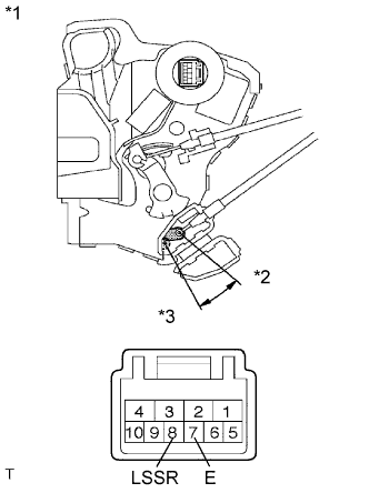
Text in Illustration *1 Component without harness connected
(Front Door Lock Assembly LH)
*2 Unlock *3 Lock Remove the front door lock assembly LH Click here.
-
Measure the resistance according to the value(s) in the table below.
Standard Resistance Tester Connection Condition Specified Condition 7 (E) - 8 (LSSR) Locked 10 kΩ or higher 7 (E) - 8 (LSSR) Unlocked Below 1 Ω
NG 
REPLACE FRONT DOOR LOCK ASSEMBLY LH Click here
OK 
-
-
CHECK HARNESS AND CONNECTOR (MAIN BODY ECU (DRIVER SIDE JUNCTION BLOCK ASSEMBLY) - FRONT DOOR LOCK ASSEMBLY LH)
-
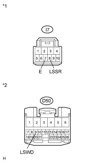
Text in Illustration *1 Front view of wire harness connector
(to Front Door Lock Assembly LH)
*2 Front view of wire harness connector
(to Main Body ECU (Driver Side Junction Block Assembly))
Disconnect the I7 front door lock assembly LH connector.
-
Disconnect D50 main body ECU (driver side junction block assembly) connector.
-
Measure the resistance according to the value(s) in the table below.
Standard Resistance Tester Connection Condition Specified Condition I7-8 (LSSR) - D50-9 (LSWD) Always Below 1 Ω I7-8 (LSSR) - Body ground Always 10 kΩ or higher I7-7 (E) - Body ground Always Below 1 Ω
NG
REPAIR OR REPLACE HARNESS OR CONNECTOR
OK
REPLACE MAIN BODY ECU (DRIVER SIDE JUNCTION BLOCK ASSEMBLY) Click here
-
-
INSPECT FRONT DOOR LOCK ASSEMBLY RH
-
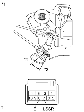
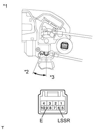
Text in Illustration *1 Component without harness connected
(Front Door Lock Assembly RH)
*2 Unlock *3 Lock Remove the front door lock assembly RH Click here.
-
Measure the resistance according to the value(s) in the table below.
Standard Resistance Tester Connection Condition Specified Condition 7 (LSSR) - 8 (E) Locked 10 kΩ or higher 7 (LSSR) - 8 (E) Unlocked Below 1 Ω
NG
REPLACE FRONT DOOR LOCK ASSEMBLY RH Click here
OK
-
-
CHECK HARNESS AND CONNECTOR (MAIN BODY ECU (DRIVER SIDE JUNCTION BLOCK ASSEMBLY) - FRONT DOOR LOCK ASSEMBLY RH)
-
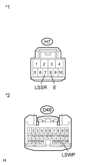
Text in Illustration *1 Front view of wire harness connector
(to Front Door Lock Assembly RH)
*2 Front view of wire harness connector
(to Main Body ECU (Driver Side Junction Block Assembly))
Disconnect the H7 front door lock assembly RH connector.
-
Disconnect the D49 main body ECU (driver side junction block assembly) connector.
-
Measure the resistance according to the value(s) in the table below.
Standard Resistance Tester Connection Condition Specified Condition H7-7 (LSSR) - D49-27 (LSWP) Always Below 1 Ω H7-7 (LSSR) - Body ground Always 10 kΩ or higher H7-8 (E) - Body ground Always Below 1 Ω
NG
REPAIR OR REPLACE HARNESS OR CONNECTOR
OK
REPLACE MAIN BODY ECU (DRIVER SIDE JUNCTION BLOCK ASSEMBLY) Click here
-
-
INSPECT REAR DOOR LOCK ASSEMBLY LH
-
Text in Illustration *1 Component without harness connected
(Rear Door Lock Assembly LH)
*2 Lock *3 Unlock Remove the rear door lock assembly LH Click here.
-
Measure the resistance according to the value(s) in the table below.
Standard Resistance Tester Connection Condition Specified Condition 6 (LSSR) - 9 (E) Locked 10 kΩ or higher 6 (LSSR) - 9 (E) Unlocked Below 1 Ω
NG
REPLACE REAR DOOR LOCK ASSEMBLY LH Click here
OK
-
-
CHECK HARNESS AND CONNECTOR (MAIN BODY ECU (DRIVER SIDE JUNCTION BLOCK ASSEMBLY) - REAR DOOR LOCK ASSEMBLY LH)
-
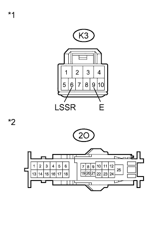
Text in Illustration *1 Front view of wire harness connector
(to Rear Door Lock Assembly LH)
*2 Front view of wire harness connector
(to Main Body ECU (Driver Side Junction Block Assembly))
Disconnect the K3 rear door lock assembly LH connector.
-
Disconnect the 2O main body ECU (driver side junction block assembly) connector.
-
Measure the resistance according to the value(s) in the table below.
Standard Resistance Tester Connection Condition Specified Condition K3-6 (LSSR) - 2O-5 Always Below 1 Ω K3-6 (LSSR) - Body ground Always 10 kΩ or higher K3-9 (E) - Body ground Always Below 1 Ω
NG
REPAIR OR REPLACE HARNESS OR CONNECTOR
OK
REPLACE MAIN BODY ECU (DRIVER SIDE JUNCTION BLOCK ASSEMBLY) Click here
-
-
INSPECT REAR DOOR LOCK ASSEMBLY RH
-
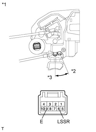
Text in Illustration *1 Component without harness connected
(Rear Door Lock Assembly RH)
*2 Lock *3 Unlock Remove the rear door lock assembly RH Click here.
-
Measure the resistance according to the value(s) in the table below.
Standard Resistance Tester Connection Condition Specified Condition 6 (LSSR) - 9 (E) Locked 10 kΩ or higher 6 (LSSR) - 9 (E) Unlocked Below 1 Ω
NG
REPLACE REAR DOOR LOCK ASSEMBLY RH Click here
OK
-
-
CHECK HARNESS AND CONNECTOR (MAIN BODY ECU (DRIVER SIDE JUNCTION BLOCK ASSEMBLY) - REAR DOOR LOCK ASSEMBLY RH)
-
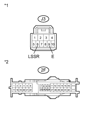
Text in Illustration *1 Front view of wire harness connector
(to Rear Door Lock Assembly RH)
*2 Front view of wire harness connector
(to Main Body ECU (Driver Side Junction Block Assembly))
Disconnect the J3 rear door lock assembly RH connector.
-
Disconnect the 2F main body ECU (driver side junction block assembly) connector.
-
Measure the resistance according to the value(s) in the table below.
Standard Resistance Tester Connection Condition Specified Condition J3-6 (LSSR) - 2F-5 Always Below 1 Ω J3-6 (LSSR) - Body ground Always 10 kΩ or higher J3-9 (E) - Body ground Always Below 1 Ω
NG
REPAIR OR REPLACE HARNESS OR CONNECTOR
OK
REPLACE MAIN BODY ECU (DRIVER SIDE JUNCTION BLOCK ASSEMBLY) Click here
-