LIGHTING SYSTEM Interior Light Circuit
DESCRIPTION
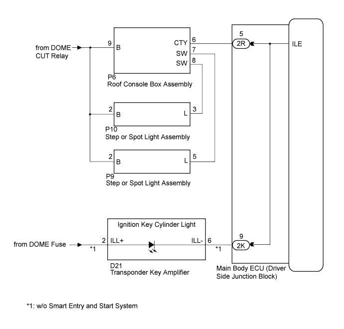
The illuminated entry system controls the roof console box assembly, step or spot light assembly and transponder key amplifier*1.
Tech Tips
*1: w/o Smart Entry and Start System
WIRING DIAGRAM
INSPECTION PROCEDURE
PROCEDURE
-
PERFORM ACTIVE TEST USING GTS
-
Connect the GTS to the DLC3.
-
Turn the ignition switch to ON.
-
Turn the GTS on.
-
Enter the following menus: Body Electrical / Main Body / Active Test.
-
Check that the lights operate.
Main Body Tester Display Test Part Control Range Diagnostic Note Illuminated Entry System Roof console box assembly, step or spot light assembly and transponder key amplifier ON/OFF Interior light switch is in the DOOR position and all doors are closed. OK Each light fades in.
NG 
INSPECT MAIN BODY ECU (DRIVER SIDE JUNCTION BLOCK ASSEMBLY) Click here
OK 
PROCEED TO NEXT SUSPECTED AREA SHOWN IN PROBLEM SYMPTOMS TABLE Click here
-
-
INSPECT MAIN BODY ECU (DRIVER SIDE JUNCTION BLOCK ASSEMBLY)
-
Measure the voltage according to the value(s) in the table below.
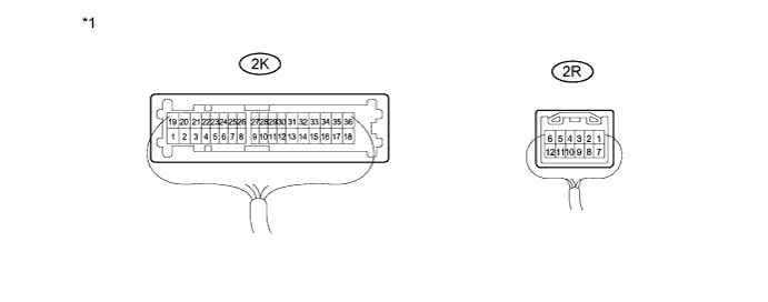
Text in Illustration *1 Component with harness connected
(Main Body ECU (Driver Side Junction Block Assembly))
- - Standard Voltage Tester Connection Condition Specified Condition 2K-9 - Body ground*1 Ignition key cylinder light off 11 to 14 V 2R-5 - Body ground Interior light switch in DOOR position and Interior lights off 11 to 14 V
-
*1: w/o Smart Entry and Start System
-
NG 
REPAIR OR REPLACE HARNESS OR CONNECTOR
OK
REPLACE MAIN BODY ECU (DRIVER SIDE JUNCTION BLOCK ASSEMBLY) Click here
-