LIGHTING SYSTEM IG Signal Circuit
DESCRIPTION
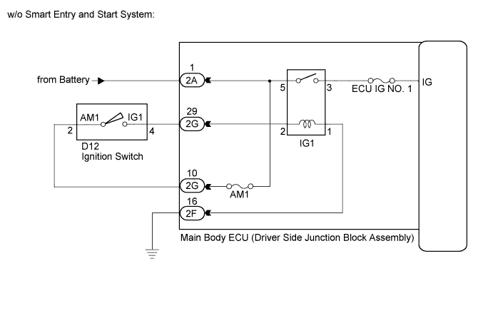
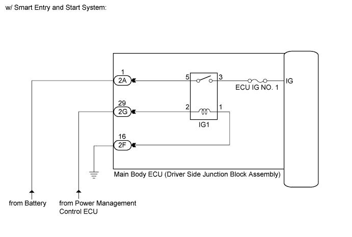
This circuit detects the ignition switch ON or off condition, and sends it to the main body ECU (driver side junction block assembly).
WIRING DIAGRAM
INSPECTION PROCEDURE
Note
Inspect the fuses for circuits related to this system before performing the following inspection procedure.
PROCEDURE
-
READ VALUE USING GTS
-
Connect the GTS to the DLC3.
-
Turn the ignition switch to ON.
-
Turn the GTS on.
-
Enter the following menus: Body Electrical / Main Body / Data List.
-
Read the display on the GTS.
Main Body Tester Display Measurement Item/Range Normal Condition Diagnostic Note IG SW Ignition switch or engine switch IG signal/ON or OFF ON: Ignition switch ON
OFF: Ignition switch off
- OK Normal conditions listed above are displayed.
NG 
INSPECT IG1 RELAY Click here
OK 
PROCEED TO NEXT SUSPECTED AREA SHOWN IN PROBLEM SYMPTOMS TABLE Click here
-
-
INSPECT IG1 RELAY
-
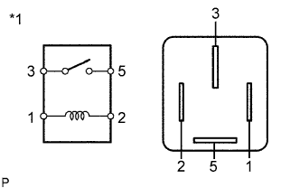
Text in Illustration *1 Component without harness connected
(IG1 Relay)
Remove the IG1 relay from the main body ECU (driver side junction block assembly).
-
Measure the resistance according to the value(s) in the table below.
Standard Resistance Tester Connection Condition Specified Condition 3 - 5 When battery voltage is not applied to terminals 1 and 2 10 kΩ or higher When battery voltage is applied to terminals 1 and 2 Below 1 Ω
NG 
REPLACE IG1 RELAY
OK 
-
-
CHECK HARNESS AND CONNECTOR (MAIN BODY ECU (DRIVER SIDE JUNCTION BLOCK ASSEMBLY) - BATTERY AND BODY GROUND)
-
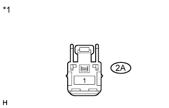
Text in Illustration *1 Front view of wire harness connector
(to Main Body ECU (Driver Side Junction Block Assembly))
Disconnect the 2A main body ECU (driver side junction block assembly) connector.
-
Measure the voltage according to the value(s) in the table below.
Standard Voltage Tester Connection Condition Specified Condition 2A-1 - Body ground Always 11 to 14 V -
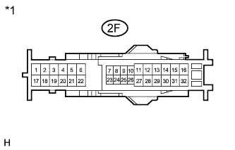
Text in Illustration *1 Front view of wire harness connector
(to Main Body ECU (Driver Side Junction Block Assembly))
Disconnect the 2F main body ECU (driver side junction block assembly) connector.
-
Measure the resistance according to the value(s) in the table below.
Standard Resistance Tester Connection Condition Specified Condition 2F-16 - Body ground Always Below 1 Ω
NG
REPAIR OR REPLACE HARNESS OR CONNECTOR
OK
-
-
CHECK VEHICLE CONDITION
-
Check the vehicle condition.
Result Condition Proceed to w/o Smart Entry and Start System A w/ Smart Entry and Start System B
B
CHECK HARNESS AND CONNECTOR (POWER MANAGEMENT CONTROL ECU - MAIN BODY ECU) Click here
A
-
-
CHECK HARNESS AND CONNECTOR (MAIN BODY ECU (DRIVER SIDE JUNCTION BLOCK ASSEMBLY) - IGNITION SWITCH)
-
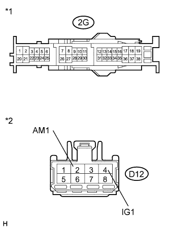
Text in Illustration *1 Front view of wire harness connector
(to Main Body ECU (Driver Side Junction Block Assembly))
*2 Front view of wire harness connector
(to Ignition Switch)
Disconnect the D12 ignition switch connector.
-
Disconnect the 2G main body ECU (driver side junction block assembly) connector.
-
Measure the resistance according to the value(s) in the table below.
Standard Resistance Tester Connection Condition Specified Condition 2G-10 - D12-2 (AM1) Always Below 1 Ω 2G-29 - D12-4 (IG1) Always Below 1 Ω 2G-10 - Body ground Always 10 kΩ or higher 2G-29 - Body ground Always 10 kΩ or higher
NG
REPAIR OR REPLACE HARNESS OR CONNECTOR
OK
-
-
INSPECT IGNITION SWITCH
-
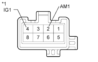
Text in Illustration *1 Component without harness connected
(Ignition Switch)
Measure the resistance according to the value(s) in the table below.
Standard Resistance Tester Connection Condition Specified Condition 2 (AM1) - 4 (IG1) Ignition switch off 10 kΩ or higher Ignition switch ON Below 1 Ω
NG
REPLACE IGNITION SWITCH Click here
OK
REPLACE MAIN BODY ECU (DRIVER SIDE JUNCTION BLOCK ASSEMBLY) Click here
-
-
CHECK HARNESS AND CONNECTOR (POWER MANAGEMENT CONTROL ECU - MAIN BODY ECU)
-
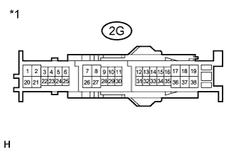
Text in Illustration *1 Front view of wire harness connector
(to Main Body ECU (Driver Side Junction Block Assembly))
Disconnect the 2G main body ECU (driver side junction block assembly) connector.
-
Measure the voltage according to the value(s) in the table below.
Standard Voltage Tester Connection Condition Specified Condition 2G-29 - Body ground Engine switch on (IG) 11 to 14 V
NG
REPAIR OR REPLACE HARNESS OR CONNECTOR
OK
REPLACE MAIN BODY ECU (DRIVER SIDE JUNCTION BLOCK ASSEMBLY) Click here
-