LIGHTING SYSTEM Engine Switch Illumination Circuit
DESCRIPTION
The illuminated entry system controls the engine switch illumination.
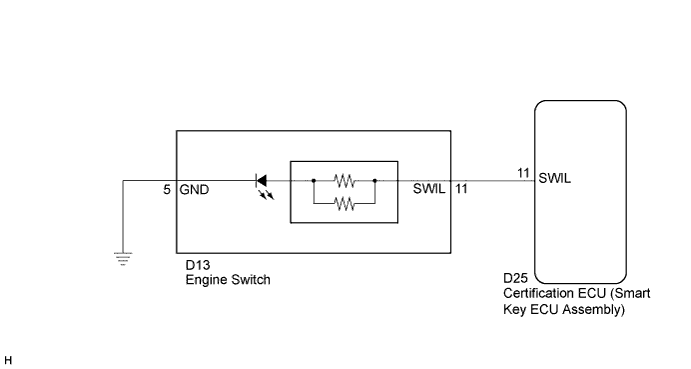
WIRING DIAGRAM
INSPECTION PROCEDURE
PROCEDURE
-
PERFORM ACTIVE TEST USING GTS
-
Connect the GTS to the DLC3.
-
Turn the ignition switch to ON.
-
Turn the GTS on.
-
Enter the following menus: Body Electrical / Entry&Start / Active Test.
-
Check that the the illumination operates.
Entry&Start Tester Display Test Part Control Range Diagnostic Note Power/Engine SW Light Engine switch illumination ON/OFF When performing this Active Test, make sure the following condition is met:
The engine switch illumination is off (15 seconds or more have elapsed since it turned from on to off) and the engine switch is on (ACC) or on (IG), or the engine is running.
OK Engine switch illumination comes on.
NG 
INSPECT ENGINE SWITCH Click here
OK 
PROCEED TO NEXT SUSPECTED AREA SHOWN IN PROBLEM SYMPTOMS TABLE Click here
-
-
INSPECT ENGINE SWITCH
-
Remove the engine switch Click here.
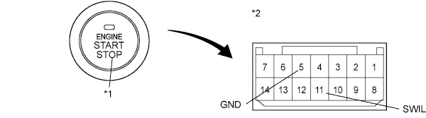
Text in Illustration *1 Illumination *2 Component without harness connected
(Engine Switch)
-
Apply battery voltage to the engine switch.
-
Check that the illumination comes on.
OK Measurement Condition Specified Condition Battery positive (+) → Terminal 11 (SWIL)
Battery negative (-) → Terminal 5 (GND)
Engine switch illumination comes on
NG 
REPLACE ENGINE SWITCH Click here
OK 
-
-
CHECK HARNESS AND CONNECTOR (ENGINE SWITCH - CERTIFICATION ECU AND BODY GROUND)
-
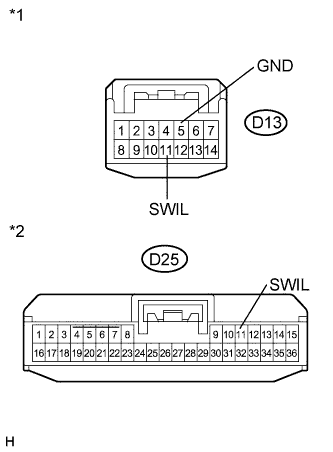
Text in Illustration *1 Front view of wire harness connector
(to Engine Switch)
*2 Front view of wire harness connector
(to Certification ECU (Smart Key ECU Assembly))
Disconnect the D25 certification ECU (smart key ECU assembly) connector.
-
Disconnect the D13 engine switch connector.
-
Measure the resistance according to the value(s) in the table below.
Standard Resistance Tester Connection Condition Specified Condition D13-11 (SWIL) - D25-11 (SWIL) Always Below 1 Ω D13-5 (GND) - Body ground Always Below 1 Ω D13-11 (SWIL) - Body ground Always 10 kΩ or higher
NG
REPAIR OR REPLACE HARNESS OR CONNECTOR
OK
REPLACE CERTIFICATION ECU (SMART KEY ECU ASSEMBLY)
-