ENGINE IMMOBILISER SYSTEM (w/o Smart Entry and Start System), Diagnostic DTC:B2784

| DTC Code | DTC Name |
|---|---|
| B2784 | Antenna Coil Open / Short |
DESCRIPTION
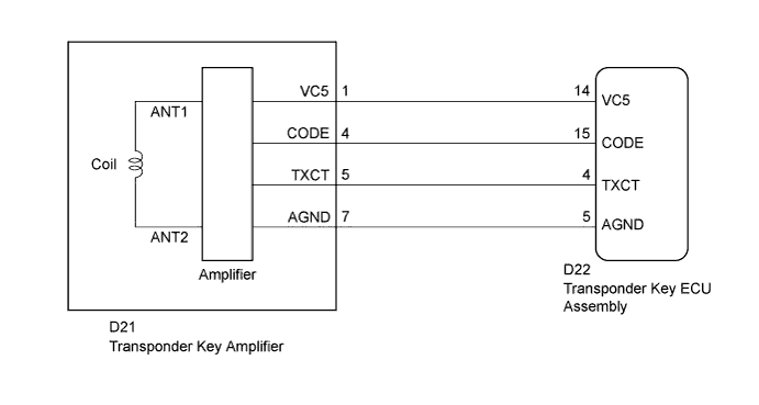
The transponder key coil is built into the transponder key amplifier and receives a key code signal from the transponder chip in the key. This signal is amplified by the amplifier, then it is output to the transponder key ECU assembly.
| DTC No. | DTC Detection Condition | Trouble Area |
|---|---|---|
| B2784 | Antenna coil is open/shorted. |
|
WIRING DIAGRAM
INSPECTION PROCEDURE
Note
If the transponder key ECU assembly is replaced, register the key and ECU communication ID (Service Bulletin).
PROCEDURE
-
READ VALUE USING GTS (KEY SW)
-
Connect the GTS to the DLC3.
-
Turn the ignition switch to ON.
-
Turn the GTS on.
-
Enter the following menus: Body Electrical / Immobiliser / Data List.
-
Read the Data List according to the display on the GTS.
Immobiliser (Transponder Key ECU Assembly) Tester Display Measurement Item/Range Normal Condition Diagnostic Note Antenna Coil Status Transponder key amplifier coil condition/Normal or Fail Normal: Antenna coil normal
Fail: Antenna coil malfunctioning
- OK On the GTS screen, the item displays Normal according to the chart above.
NG 
CHECK HARNESS AND CONNECTOR (TRANSPONDER KEY ECU - TRANSPONDER KEY AMPLIFIER) Click here
OK 
REPLACE TRANSPONDER KEY ECU ASSEMBLY
-
-
CHECK HARNESS AND CONNECTOR (TRANSPONDER KEY ECU - TRANSPONDER KEY AMPLIFIER)
-
Disconnect the transponder key ECU assembly connector.
-
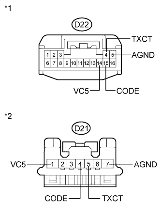
Text in Illustration *1 Front view of wire harness connector
(to Transponder Key ECU Assembly)
*2 Front view of wire harness connector
(to Transponder Key Amplifier)
Disconnect the transponder key amplifier connector.
-
Measure the resistance according to the value(s) in the table below.
Standard Resistance Tester Connection Condition Specified Condition D22-4 (TXCT) - D21-5 (TXCT) Always Below 1 Ω D22-5 (AGND) - D21-7 (AGND) Always Below 1 Ω D22-14 (VC5) - D21-1 (VC5) Always Below 1 Ω D22-15 (CODE) - D21-4 (CODE) Always Below 1 Ω D22-4 (TXCT) - Body ground Always 10 kΩ or higher D22-5 (AGND) - Body ground Always 10 kΩ or higher D22-14 (VC5) - Body ground Always 10 kΩ or higher D22-15 (CODE) - Body ground Always 10 kΩ or higher D21-5 (TXCT) - Body ground Always 10 kΩ or higher D21-7 (AGND) - Body ground Always 10 kΩ or higher D21-1 (VC5) - Body ground Always 10 kΩ or higher D21-4 (CODE) - Body ground Always 10 kΩ or higher
NG 
REPAIR OR REPLACE HARNESS OR CONNECTOR
OK 
-
-
INSPECT TRANSPONDER KEY AMPLIFIER (POWER SOURCE AND GROUND)
-
Reconnect the transponder key ECU assembly connector.
-
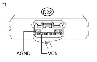
Text in Illustration *1 Component with harness connected
(Transponder Key ECU Assembly)
Reconnect the transponder key amplifier connector.
-
Measure the voltage and resistance according to the value(s) in the table below.
Standard Voltage Tester Connection Condition Specified Condition D22-14 (VC5) - Body ground No key is in ignition key cylinder Below 1 V D22-14 (VC5) - Body ground Key is in ignition key cylinder 4.6 to 5.4 V Standard Resistance Tester Connection Condition Specified Condition D22-5 (AGND) - Body ground Always Below 1 Ω
NG
REPLACE TRANSPONDER KEY ECU ASSEMBLY
OK
REPLACE TRANSPONDER KEY AMPLIFIER Click here
-