THEFT DETERRENT SYSTEM (w/ Smart Entry and Start System) TERMINALS OF ECU

-
CHECK MAIN BODY ECU (DRIVER SIDE JUNCTION BLOCK ASSEMBLY)
-
Disconnect the main body ECU (driver side junction block assembly) connectors.
-
Measure the resistance and voltage according to the value(s) in the table below.
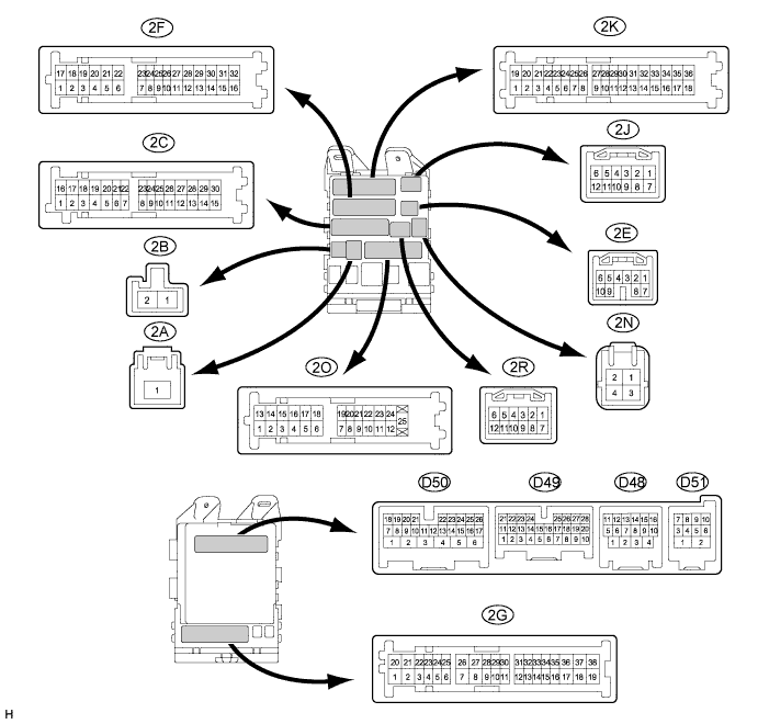
Tester Connection Wiring Color Terminal Description Condition Specified Condition D49-7 (RCTY) - Body ground GR - Body ground Rear courtesy light switch RH input Rear door RH closed (OFF) → open (ON) 10 kΩ or higher → Below 1 Ω D49-21 (PCTY) - Body ground V - Body ground Passenger side courtesy light switch input Passenger side door closed (OFF) → open (ON) 10 kΩ or higher → Below 1 Ω D49-25 (BCTY) - Body ground GR - Body ground Back door courtesy light switch input Back door closed (OFF) → open (ON) 10 kΩ or higher → Below 1 Ω D50-16 (HCTY) - Body ground BE - Body ground Security courtesy switch Engine hood closed (OFF) → open (ON) 10 kΩ or higher → Below 1 Ω D50-24 (DCTY) - Body ground V - Body ground Driver side door courtesy light switch input Driver side door closed (OFF) → open (ON) 10 kΩ or higher → Below 1 Ω 2A-1 (ACC) - Body ground B - Body ground Ignition power supply (ACC signal) Engine switch on (ACC) → OFF 11 to 14 V → Below 1 V 2A-1 (IG) - Body ground B - Body ground Ignition power supply (IG signal) Engine switch on (IG) → OFF 11 to 14 V → Below 1 V 2C-30 (ALTB) - Body ground BR - Body ground +B (power system alternator system) power supply Always 11 to 14 V 2F-16 (GND1) - Body ground W-B - Body ground Ground Always Below 1 Ω 2C-24 (BECU) - Body ground L - Body ground +B power supply Always 11 to 14 V 2C-24 (BECU) - Body ground L - Body ground +B power supply Always 11 to 14 V 2O-19 (LCTY) - Body ground R - Body ground Rear courtesy light switch LH input Rear door LH closed (OFF) → open (ON) 10 kΩ or higher → Below 1 Ω If the result is not as specified, there may be a malfunction in the wire harness.
Tech Tips
Measure values on the wire harness side with the connectors disconnected.
-
Reconnect the main body ECU (driver side junction block assembly) connectors.
-
Measure the voltage according to the value(s) in the table below.
Tester Connection Wiring Color Terminal Description Condition Specified Condition D48-4 (HAZ) - Body ground G - Body ground Turn signal flasher relay signal System in alarm sounding state Below 1 V D51-4 (IND) - Body ground SB - Body ground Security indicator output Security indicator on
(It lights up only in arming preparation state or alarm sounding state. It flashes when immobiliser is operating.)
3 to 6 V D51-6 (SH) - Body ground BR - Body ground Security horn drive Security horn sounding Pulse generation
(Below 1 V ← → 12 V)
2C-25 (HORN) - Body ground R - Body ground Vehicle horn drive Vehicle horn sounding
(Theft deterrent system in alarm sounding state)
Pulse generation
(Below 1 V ← → 12 V)
If the result is not as specified, the main body ECU (driver side junction block assembly) may have a malfunction.
-