ENGINE IMMOBILISER SYSTEM (w/ Smart Entry and Start System) TERMINALS OF ECU

-
CHECK ENGINE SWITCH
-
Disconnect the D13 engine switch connector.

-
Measure the resistance according to the value(s) in the table below.
Tech Tips
Measure the values on the wire harness side with connector disconnected.
Tester Connection Wiring Color Terminal Description Condition Specified Condition D13-8 (AGND) - Body ground V - Body ground Ground Always Below 1 Ω If the result is not as specified, there may be a malfunction in the wire harness.
-
Reconnect the D13 engine switch connector.
-
Measure the voltage according to the value(s) in the table below.
Tester Connection Wiring Color Terminal Description Condition Specified Condition D13-9 (TXCT) - D13-8 (AGND) GR - V Key code output signal
-
Engine switch off
-
30 seconds after door opened and closed
-
Brake pedal not depressed
Below 1 V D13-9 (TXCT) - D13-8 (AGND) GR - V Key code output signal
-
Engine switch off
-
Key not in cabin
-
Engine switch pressed within 30 seconds
Pulse generation
(See waveform 1)
D13-10 (CODE) - D13-8 (AGND) LG - V Demodulated signal of key code data
-
Engine switch off
-
30 seconds after door opened and closed
-
Brake pedal not depressed
Below 1 V D13-10 (CODE) - D13-8 (AGND) LG - V Demodulated signal of key code data
-
Engine switch off
-
Key battery removed
-
Engine switch touched with key and pressed
Pulse generation
(See waveform 2)
D13-14 (VC5) - D13-8 (AGND) R - V Power supply
-
Engine switch off
-
30 seconds after door opened and closed
-
Brake pedal not depressed
Below 1 V D13-14 (VC5) - D13-8 (AGND) R - V Power supply
-
Engine switch off
-
Key not in cabin
-
Engine switch pressed within 30 seconds
Pulse generation
(See waveform 3)
If the result is not as specified, the engine switch may be malfunctioning.
-
-
Inspect using an oscilloscope.
-
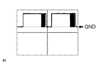
Waveform 1 (Reference)
Item Content Tester Connection D13-9 (TXCT) - D13-8 (AGND) Tool Setting 2 V/DIV., 50 ms./DIV. Condition
-
Engine switch off
-
Key not in cabin
-
Engine switch pressed within 30 seconds
-
-
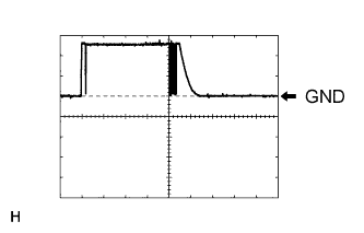
Waveform 2 (Reference)
Item Content Tester Connection D13-10 (CODE) - D13-8 (AGND) Tool Setting 2 V/DIV., 50 ms./DIV. Condition
-
Engine switch off
-
Key battery removed
-
Engine switch touched with key and pressed
-
-
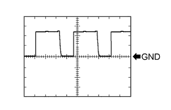
Waveform 3 (Reference)
Item Content Tester Connection D13-14 (VC5) - D13-8 (AGND) Tool Setting 2 V/DIV., 200 ms./DIV. Condition
-
Engine switch off
-
Key not in cabin
-
Engine switch pressed within 30 seconds
-
-
-
-
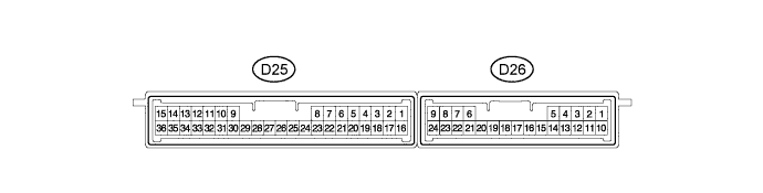
CHECK CERTIFICATION ECU (SMART KEY ECU ASSEMBLY)
-
Disconnect the D25 certification ECU (smart key ECU assembly) connector.
-
Measure the resistance and voltage according to the value(s) in the table below.
Tech Tips
Measure the values on the wire harness side with connector disconnected.
Tester Connection Wiring Color Terminal Description Condition Specified Condition D25-1 (+B) - D25-15 (E) G - B +B power supply Always 11 to 14 V D25-15 (E) - Body ground B - Body ground Ground Always Below 1 Ω If the result is not as specified, there may be a malfunction in the wire harness.
-
Reconnect the D25 certification ECU (smart key ECU assembly) connector.
-
Measure the resistance and voltage according to the value(s) in the table below.
Tester Connection Wiring Color Terminal Description Condition Specified Condition D25-2 (INDS) - Body ground Y - Body ground Security indicator light signal Engine switch on (IG), security indicator light off Below 2 V D25-2 (INDS) - Body ground Y - Body ground Security indicator light signal Engine switch off, security indicator light blinks Pulse generation D25-12 (TXCT) - D25-36 (AGND) GR - V Engine switch TXCT output
-
Engine switch off
-
30 seconds after door opened and closed
-
Brake pedal not depressed
Below 1 V D25-12 (TXCT) - D25-36 (AGND) GR - V Engine switch TXCT output
-
Engine switch off
-
Key not in cabin
-
Engine switch pressed within 30 seconds
Pulse generation
(See waveform 1)
D25-13 (CODE) - D25-36 (AGND) LG - V Engine switch CODE input
-
Engine switch off
-
30 seconds after door opened and closed
-
Brake pedal not depressed
Below 1 V D25-13 (CODE) - D25-36 (AGND) LG - V Engine switch CODE input
-
Engine switch off
-
Key battery removed
-
Engine switch touched with key and pressed
Pulse generation
(See waveform 2)
D25-16 (IG) - D25-15 (E) R - B Ignition power supply Engine switch off Below 1 V D25-16 (IG) - D25-15 (E) R - B Ignition power supply Engine switch on (IG) 11 to 14 V D25-28 (VC5) - D25-36 (AGND) R - V Engine switch power supply
-
Engine switch off
-
30 seconds after door opened and closed
-
Brake pedal not depressed
Below 1 V D25-28 (VC5) - D25-36 (AGND) R - V Engine switch power supply
-
Engine switch off
-
Key not in cabin
-
Engine switch pressed within 30 seconds
Pulse generation
(See waveform 3)
D25-34 (EFII) - D25-15 (E) BR - B ECM input signal Engine switch off 11 to 14 V D25-34 (EFII) - D25-15 (E) BR - B ECM input signal Within 3 seconds after the starter operates and initial combustion occurs, or within 3 seconds after engine switch first turned on (IG) after battery disconnected and connected Pulse generation
(See waveform 4)
D25-35 (EFIO) - D25-15 (E) G - B ECM output signal Engine switch off 11 to 14 V D25-35 (EFIO) - D25-15 (E) G - B ECM output signal Engine switch on (IG) Pulse generation
(See waveform 5)
D25-36 (AGND) - Body ground V - Body ground Engine switch ground Always Below 1 Ω If the result is not as specified, the certification ECU (smart key ECU assembly) may be malfunctioning.
-
-
Inspect using an oscilloscope.
-
Waveform 1 (Reference)
Item Content Tester Connection D25-12 (TXCT) - D25-36 (AGND) Tool Setting 2 V/DIV., 50 ms./DIV. Condition
-
Engine switch off
-
Key not in cabin
-
Engine switch pressed within 30 seconds
-
-
Waveform 2 (Reference)
Item Content Tester Connection D25-13 (CODE) - D25-36 (AGND) Tool Setting 2 V/DIV., 50 ms./DIV. Condition
-
Engine switch off
-
Key battery removed
-
Engine switch touched with key and pressed
-
-
Waveform 3 (Reference)
Item Content Tester Connection D25-28 (VC5) - D25-36 (AGND) Tool Setting 2 V/DIV., 200 ms./DIV. Condition
-
Engine switch off
-
Key not in cabin
-
Engine switch pressed within 30 seconds
-
-
Waveform 4 (Reference)
Item Content Tester Connection D25-34 (EFII) - D25-15 (E) Tool Setting 5 V/DIV., 500 ms/DIV. Condition Within 3 seconds after the starter operates and initial combustion occurs, or within 3 seconds after engine switch first turned on (IG) after battery disconnected and connected -
Waveform 5 (Reference)
Item Content Tester Connection D25-35 (EFIO) - D25-15 (E) Tool Setting 5 V/DIV., 100 ms./DIV. Condition Engine switch on (IG)
-
-
-
CHECK STEERING LOCK ECU (STEERING LOCK ACTUATOR ASSEMBLY)
-
Disconnect the D17 steering lock ECU (steering lock actuator assembly) connector.

-
Measure the resistance and voltage according to the value(s) in the table below.
Tech Tips
Measure the values on the wire harness side with connector disconnected.
Tester Connection Wiring Color Terminal Description Condition Specified Condition D17-1 (GND) - Body ground W-B - Body ground Ground Always Below 1 Ω D17-6 (IG2) - Body ground LG - Body ground Ignition power supply Engine switch off Below 1 V D17-6 (IG2) - Body ground LG - Body ground Ignition power supply Engine switch on (IG) 11 to 14 V D17-7 (B) - Body ground P - Body ground +B power supply Always 11 to 14 V If the result is not as specified, there may be a malfunction in the wire harness.
-
-
CHECK ECM
-
The values listed under "Specified Condition" are reference values. Because waterproof connectors are used for ECM, inspections cannot be performed with the connectors connected.
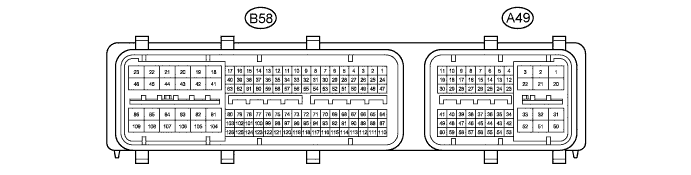
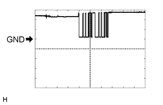
Tester Connection Wiring Color Terminal Description Condition Specified Condition B58-104 (E1) - Body ground BR - Body ground Ground Always Below 1 Ω A49-10 (IMO) - B58-104 (E1) BR - BR Certification ECU (smart key ECU assembly) output signal Engine switch off 11 to 14 V A49-10 (IMO) - B58-104 (E1) BR - BR Certification ECU (smart key ECU assembly) output signal Within 3 seconds after the starter operates and initial combustion occurs, or within 3 seconds after engine switch first turned on (IG) after battery disconnected and connected Pulse generation
(See waveform 1)
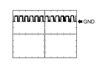
A49-11 (IMI) - B58-104 (E1) G - BR Certification ECU (smart key ECU assembly) input signal Engine switch off Below 1 V A49-11 (IMI) - B58-104 (E1) G - BR Certification ECU (smart key ECU assembly) input signal Engine switch on (IG) Pulse generation
(See waveform 2)
-
Waveform:
-
Waveform 1 (Reference)
Item Content Tester Connection A49-10 (IMO) - B58-104 (E1) Tool Setting 5 V/DIV., 500 ms./DIV. Condition Within 3 seconds after the starter operates and initial combustion occurs, or within 3 seconds after engine switch first turned on (IG) after battery disconnected and connected -
Waveform 2 (Reference)
Item Content Tester Connection A49-11 (IMI) - B58-104 (E1) Tool Setting 5 V/DIV., 100 ms./DIV. Condition Engine switch on (IG)
-
-
-
CHECK POWER MANAGEMENT CONTROL ECU
-
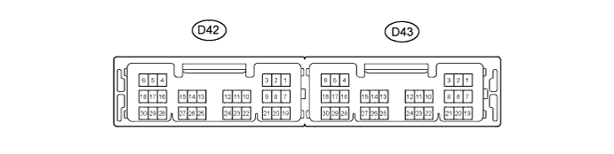
Disconnect the D43 power management control ECU connector.
-
Measure the resistance and voltage according to the value(s) in the table below.
Tech Tips
Measure the values on the wire harness side with connector disconnected.
Tester Connection Wiring Color Terminal Description Condition Specified Condition D43-1 (AM22) - Body ground LG - Body ground Battery Always 11 to 14 V D43-2 (AM21) - Body ground Y - Body ground Battery Always 11 to 14 V D43-5 (GND2) - Body ground W-B - Body ground Ground Always Below 1 Ω D43-6 (GND) - Body ground W - Body ground Ground Always Below 1 Ω If the result is not as specified, there may be a malfunction in the wire harness.
-
-
ACCESSORY METER ASSEMBLY
-
Disconnect the F2 accessory meter assembly connector.

-
Measure the voltage and resistance according to the value(s) in the table below.
Tech Tips
Measure the values on the wire harness side with connector disconnected.
Terminal No. (Symbol) Wiring Color Terminal Description Condition Specified Condition F2-1 (B) - Body ground P - Body ground Battery Always 11 to 14 V F2-12 (E) - Body ground B - Body ground Ground Always Below 1 Ω If the result is not as specified, there may be a malfunction in the wire harness.
-
Reconnect the F2 accessory meter assembly connector.
-
Measure the voltage and resistance according to the value(s) in the table below.
Terminal No. (Symbol) Wiring Color Terminal Description Condition Specified Condition F2-14 (LP) - Body ground Y - Body ground Security indicator light signal Engine switch on (IG), security indicator light off Below 2 V F2-14 (LP) - Body ground Y - Body ground Security indicator light signal Engine switch off, security indicator light blinks Pulse generation If the result is not as specified, the accessory meter assembly may be malfunctioning.
-