SMART ENTRY AND START SYSTEM (for Start Function) Power Source Mode does not Change to ON (IG and ACC)
DESCRIPTION
When the engine switch is pushed with the electrical key in the cabin, the power management control ECU receives signals to change the power source mode.
Tech Tips
To allow use of the GTS to inspect the push-button start function when the power source mode is off, repeat opening and closing any of the doors. Opening and closing a door establishes communication between the GTS and the power management control ECU. (Opening and closing a door can also be simulated by operating a door courtesy light switch.)
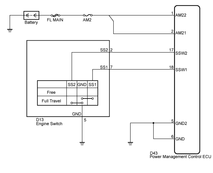
WIRING DIAGRAM
INSPECTION PROCEDURE
PROCEDURE
-
CHECK DTC
-
Connect the GTS to the DLC3.
-
Turn the GTS on.
-
Turn on and off any of the door courtesy light switches repeatedly at 1.5-second intervals or less until communication between the GTS and vehicle starts.
-
Enter the following menus: Body Electrical / All ECUs / Health Check.
-
Clear the DTC.
-
Check for DTCs again.
OK DTCs are not output.
NG 
GO TO DIAGNOSTIC TROUBLE CODE CHART
OK 
-
-
CHECK SMART ENTRY AND START SYSTEM
-
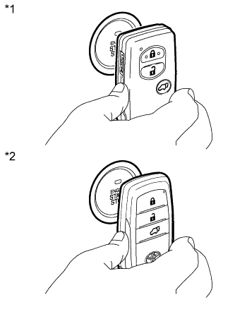
Text in Illustration *1 Type A *2 Type B Remove the battery of the electrical key transmitter Click here.
-
Touch the logo side mark of the key or card key to the engine switch.
-
Check that the engine switch can be turned on (IG).
OK Power source mode can be changed.
NG
GO TO OTHER FLOW CHART (Room Oscillator does not Recognize Key) Click here
OK
-
-
CHECK HARNESS AND CONNECTOR (BATTERY - POWER MANAGEMENT CONTROL ECU)
-
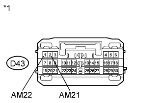
Text in Illustration *1 Front view of wire harness connector
(to Power Management Control ECU)
Disconnect the D43 connector from the power management control ECU.
-
Measure the voltage according to the value(s) in the table below.
Standard Voltage Tester Connection Condition Specified Condition D43-1 (AM22) - Body ground Always 9.5 to 16 V D43-2 (AM21) - Body ground Always 9.5 to 16 V
NG
REPAIR OR REPLACE HARNESS OR CONNECTOR (BATTERY - POWER MANAGEMENT CONTROL ECU)
OK
-
-
CHECK HARNESS AND CONNECTOR (POWER MANAGEMENT CONTROL ECU - BODY GROUND)
-
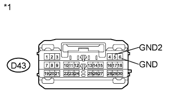
Text in Illustration *1 Front view of wire harness connector
(to Power Management Control ECU)
Disconnect the D43 connector from the power management control ECU.
-
Measure the resistance according to the value(s) in the table below.
Standard Resistance Tester Connection Condition Specified Condition D43-5 (GND2) - Body ground Always Below 1 Ω D43-6 (GND) - Body ground Always Below 1 Ω
NG
REPAIR OR REPLACE HARNESS OR CONNECTOR (POWER MANAGEMENT CONTROL ECU - BODY GROUND)
OK
-
-
READ VALUE USING GTS (START SWITCH1, START SWITCH2)
-
Reconnect the D43 connector to the power management control ECU.
-
Enter the following menus: Body Electrical / Power Source Control / Data List.
-
Read the Data List according to the display on the GTS.
Power Source Control Tester Display Measurement Item/Range Normal Condition Diagnostic Note Start Switch1 Start switch 1/ON or OFF ON: Engine switch pushed
OFF: Engine switch not pushed
- Start Switch2 Start switch 2/ON or OFF ON: Engine switch pushed
OFF: Engine switch not pushed
- OK ON (engine switch is pushed) and OFF (engine switch is not pushed) appear on the screen.
NG 
INSPECT ENGINE SWITCH Click here
OK 
REPLACE POWER MANAGEMENT CONTROL ECU Click here
-
-
INSPECT ENGINE SWITCH
-
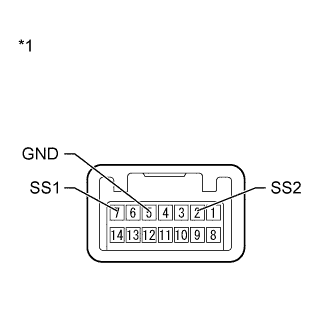
Text in Illustration *1 Component without harness connected
(Engine Switch)
Remove the engine switch Click here.
-
Measure the resistance according to the value(s) in the table below.
Standard Resistance Tester Connection Condition Specified Condition 7 (SS1) - 5 (GND) Pushed Below 1 Ω 2 (SS2) - 5 (GND) Pushed Below 1 Ω 7 (SS1) - 5 (GND) Not pushed 10 kΩ or higher 2 (SS2) - 5 (GND) Not pushed 10 kΩ or higher
NG
REPLACE ENGINE SWITCH Click here
OK
-
-
CHECK HARNESS AND CONNECTOR (ENGINE SWITCH - POWER MANAGEMENT CONTROL ECU AND BODY GROUND)
-
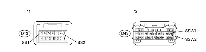
Disconnect the D43 connector from power management control ECU.
-
Measure the resistance according to the value(s) in the table below.
Standard Resistance Tester Connection Condition Specified Condition D13-7 (SS1) - D43-18 (SSW1) Always Below 1 Ω D13-7 (SS1) - Body ground Always 10 kΩ or higher D13-2 (SS2) - D43-17 (SSW2) Always Below 1 Ω D13-2 (SS2) - Body ground Always 10 kΩ or higher Text in Illustration *1 Front view of wire harness connector
(to Engine Switch)
*2 Front view of wire harness connector
(to Power Management Control ECU)
NG
REPAIR OR REPLACE HARNESS OR CONNECTOR (ENGINE SWITCH - POWER MANAGEMENT CONTROL ECU OR BODY GROUND)
OK
REPLACE POWER MANAGEMENT CONTROL ECU Click here
-