ENGINE IMMOBILISER SYSTEM (w/o Smart Entry and Start System) ECU Power Source Circuit
DESCRIPTION
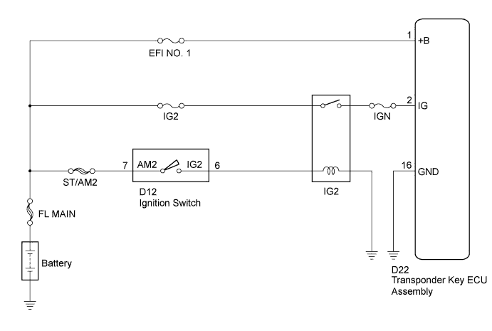
This circuit provides power to operate the transponder key ECU assembly.
WIRING DIAGRAM
INSPECTION PROCEDURE
Note
If the transponder key ECU assembly is replaced, register the key and ECU communication ID (Refer to Service Bulletin).
PROCEDURE
-
CHECK HARNESS AND CONNECTOR (TRANSPONDER KEY ECU - BATTERY AND BODY GROUND)
-
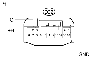
Text in Illustration *1 Front view of wire harness connector
(to Transponder Key ECU Assembly)
Disconnect the transponder key ECU assembly connector.
-
Measure the voltage and resistance according to the value(s) in the table below.
Standard Voltage Tester Connection Condition Specified Condition D22-1 (+B) - Body ground Always 11 to 14 V D22-2 (IG) - Body ground Ignition switch off Below 1 V D22-2 (IG) - Body ground Ignition switch ON 11 to 14 V Standard Resistance Tester Connection Condition Specified Condition D22-16 (GND) - Body ground Always Below 1 Ω
NG 
REPAIR OR REPLACE HARNESS OR CONNECTOR, OR REPLACE FUSE
OK 
PROCEED TO NEXT SUSPECTED AREA SHOWN IN PROBLEM SYMPTOMS TABLE Click here
-