ENGINE IMMOBILISER SYSTEM (w/o Smart Entry and Start System) Door Courtesy Switch Circuit
DESCRIPTION
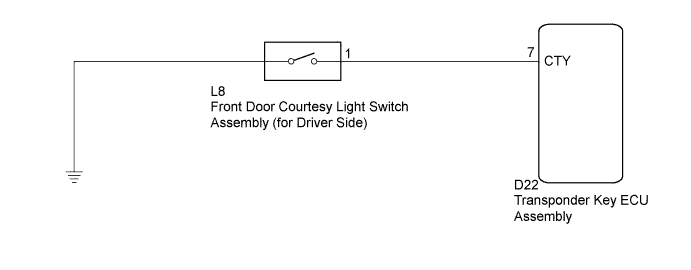
When an additional transponder key is registered, the transponder key ECU assembly detects the front door courtesy light switch assembly (for driver side) open/close condition, and enters the key registration mode.
WIRING DIAGRAM
INSPECTION PROCEDURE
Note
If the transponder key ECU assembly is replaced, register the key and ECU communication ID (Refer to Service Bulletin).
PROCEDURE
-
CHECK HARNESS AND CONNECTOR (FRONT DOOR COURTESY LIGHT SWITCH CIRCUIT)
-
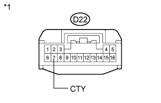
Text in Illustration *1 Front view of wire harness connector
(to Transponder Key ECU Assembly)
Disconnect the transponder key ECU assembly connector.
-
Measure the resistance according to the value(s) in the table below.
Standard Resistance Tester Connection Switch Condition Specified Condition D22-7 (CTY) - Body ground Courtesy switch pushed
(Door closed)
10 kΩ or higher D22-7 (CTY) - Body ground Courtesy switch free
(Door open)
Below 1 Ω
NG 
INSPECT FRONT DOOR COURTESY LIGHT SWITCH ASSEMBLY (for Driver Side) Click here
OK 
REPLACE TRANSPONDER KEY ECU ASSEMBLY
-
-
INSPECT FRONT DOOR COURTESY LIGHT SWITCH ASSEMBLY (for Driver Side)
-
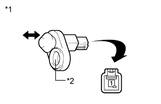
Text in Illustration *1 Component without harness connected
(Front Door Courtesy Light Switch Assembly (for Driver Side))
*2 Switch Body Remove the front door courtesy light switch assembly (for driver side) Click here.
-
Measure the resistance according to the value(s) in the table below.
Standard Resistance Tester Connection Switch Condition Specified Condition 1 - Switch body Courtesy switch pushed
(Door closed)
10 kΩ or higher 1 - Switch body Courtesy switch free
(Door open)
Below 1 Ω
NG 
REPLACE FRONT DOOR COURTESY LIGHT SWITCH ASSEMBLY (for Driver Side) Click here
OK
REPAIR OR REPLACE HARNESS OR CONNECTOR (TRANSPONDER KEY ECU - FRONT DOOR COURTESY LIGHT SWITCH)
-