ENGINE IMMOBILISER SYSTEM (w/o Smart Entry and Start System) Security Indicator Light Circuit
DESCRIPTION
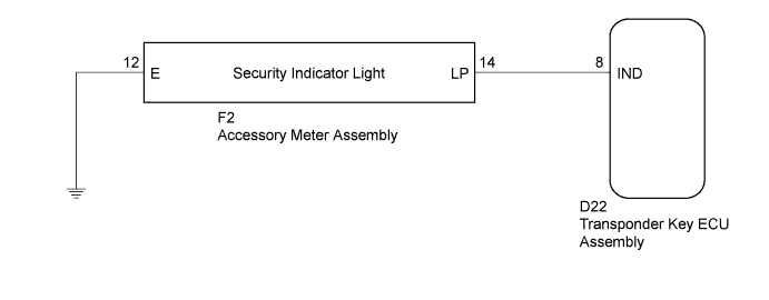
The security indicator light blinks continuously due to a continuous signal received from the transponder key ECU assembly while in the armed state.
WIRING DIAGRAM
INSPECTION PROCEDURE
Note
If the transponder key ECU assembly is replaced, register the key and ECU communication ID (Refer to Service Bulletin).
PROCEDURE
-
PERFORM ACTIVE TEST USING GTS (SECURITY INDICATOR)
-
Connect the GTS to the DLC3.
-
Turn the ignition switch to ON.
-
Turn the GTS on.
-
Enter the following menus: Body Electrical / Immobiliser / Active Test.
-
Perform the Active Test according to the display on the GTS.
Immobiliser (Transponder Key ECU Assembly) Tester Display Test Part Control Range Diagnostic Note Security Indicator Security indicator light ON/OFF - OK The security indicator turns on and off according to operation via the GTS.
NG 
CHECK HARNESS AND CONNECTOR (TRANSPONDER KEY ECU - ACCESSORY METER) Click here
OK 
REPLACE TRANSPONDER KEY ECU ASSEMBLY
-
-
CHECK HARNESS AND CONNECTOR (TRANSPONDER KEY ECU - ACCESSORY METER)
-
Disconnect the transponder key ECU assembly connector.
-
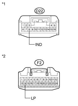
Text in Illustration *1 Front view of wire harness connector
(to Transponder Key ECU Assembly)
*2 Front view of wire harness connector
(to Accessory Meter Assembly)
Disconnect the accessory meter assembly connector.
-
Measure the resistance according to the value(s) in the table below.
Standard Resistance Tester Connection Condition Specified Condition D22-8 (IND) - F2-14 (LP) Always Below 1 Ω D22-8 (IND) - Body ground Always 10 kΩ or higher F2-14 (LP) - Body ground Always 10 kΩ or higher
NG 
REPAIR OR REPLACE HARNESS OR CONNECTOR
OK 
-
-
CHECK HARNESS AND CONNECTOR (ACCESSORY METER - BODY GROUND)
-
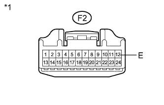
Text in Illustration *1 Front view of wire harness connector
(to Accessory Meter Assembly)
Measure the resistance according to the value(s) in the table below.
Standard Resistance Tester Connection Condition Specified Condition F2-12 (E) - Body ground Always Below 1 Ω
NG
REPAIR OR REPLACE HARNESS OR CONNECTOR
OK
REPLACE ACCESSORY METER ASSEMBLY Click here
-