SMART ENTRY AND START SYSTEM (for Entry Function) Room Oscillator does not Recognize Key
DESCRIPTION
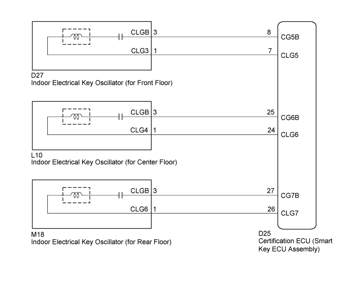
If the room oscillator does not recognize a key, one of the following may be the cause: 1) communication between the indoor electrical key oscillator (for front floor) and key cannot be performed; 2) communication between the indoor electrical key oscillator (for center floor) and key cannot be performed; or 3) communication between the indoor electrical key oscillator (for rear floor) and key cannot be performed.
WIRING DIAGRAM
INSPECTION PROCEDURE
Note
-
The smart entry and start system (for entry function) uses a multiplex communication system (LIN communication system) and CAN communication system. Inspect the communication function by following How to Proceed with Troubleshooting Click here. Troubleshoot the smart entry and start system (for entry function) after confirming that the communication system is functioning properly.
-
When using the GTS with the engine switch off to troubleshoot: Connect the GTS to the DLC3, and turn a courtesy light switch on and off at 1.5-second intervals until communication between the GTS and vehicle begins.
-
Before replacing the certification ECU (smart key ECU assembly), refer to Service Bulletin.
PROCEDURE
-
CHECK SMART ENTRY AND START SYSTEM (for Start Function)
-
Remove the battery of the key Click here.
-
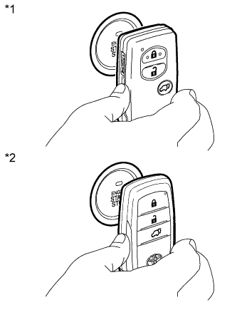
Text in Illustration *1 Type A *2 Type B With the brake pedal depressed, touch the engine switch while facing the logo side of the key to the engine switch.
-
When operating the engine switch, check whether the power source mode changes.
OK Power source mode changes. Tech Tips
-
When the key cannot be verified even though it is within the specified range, the engine start check can be performed by removing the transmitter battery from the key and holding the transmitter close to the engine switch.
-
When performing the check, if the power source mode changes, there is a problem with key certification inside the cabin.
-
NG 
GO TO SMART ENTRY AND START SYSTEM (for Start Function) (Proceed to How to Proceed with Troubleshooting) Click here
OK 
-
-
CHECK WAVE ENVIRONMENT
-
Install the battery to the key Click here.
-
Bring the key near the indoor electrical key oscillator (for front floor), and check that the engine can be started.
Note
If the key is brought within 0.2 m (0.656 ft.) of the indoor electrical key oscillator (for front floor), communication is not possible.
-
Bring the key near the indoor electrical key oscillator (for center floor), and check that the engine can be started.
Note
If the key is brought within 0.2 m (0.656 ft.) of the indoor electrical key oscillator (for center floor), communication is not possible.
-
Bring the key near the indoor electrical key oscillator (for rear floor), and check that the engine can be started*.
*: If the customize setting for Ignition Available Area is not set All, the engine will not start. Before performing this inspection, check that All has been selected Click here.
Note
If the key is brought within 0.2 m (0.656 ft.) of the indoor electrical key oscillator (for rear floor), communication is not possible.
Tech Tips
-
When the key is brought near the indoor electrical key oscillator, the possibility of wave interference decreases, and it can be determined if wave interference is causing the problem symptom.
-
If the operation is normal, the possibility of wave interference is high. Also, added vehicle components may cause wave interference. If installed, remove them and perform the operation check.
OK The engine starts. -
NG 
PERFORM KEY DIAGNOSTIC MODE INSPECTION Click here
OK 
AFFECTED BY WAVE INTERFERENCE
-
-
PERFORM KEY DIAGNOSTIC MODE INSPECTION
-
Diagnostic mode inspection (indoor electrical key oscillator (for front floor))
-
Connect the GTS to the DLC3.
-
Turn the engine switch on (IG).
-
Turn the GTS on.
-
Enter the following menus: Body Electrical / Entry&Start / Utility / Communication Check (Key Diag Mode) / Overhead + Front Room.
-
When the key is placed on the driver seat or front passenger seat cushion, check that the wireless door lock buzzer sounds.
-
-
Diagnostic mode inspection (indoor electrical key oscillator (for center floor))
-
Connect the GTS to the DLC3.
-
Turn the engine switch on (IG).
-
Turn the GTS on.
-
Enter the following menus: Body Electrical / Entry&Start / Utility / Communication Check (Key Diag Mode) / Overhead + Rear Room.
-
When the key is placed on the rear seat cushion, check that the wireless door lock buzzer sounds.
-
-
Diagnostic mode inspection (indoor electrical key oscillator (for rear floor))
-
Connect the GTS to the DLC3.
-
Turn the engine switch on (IG).
-
Turn the GTS on.
-
Enter the following menus: Body Electrical / Entry&Start / Utility / Communication Check (Key Diag Mode) / Overhead + Back Door (inside).
-
When the key is held at the same height as the rear bumper upper surface and aligned with the center of the rear of the vehicle, check that the wireless door lock buzzer sounds.
Tech Tips
If the buzzer sounds, it can be determined that the indoor electrical key oscillators are operating normally.
Result Result Proceed to Wireless door lock buzzer does not sound only for indoor electrical key oscillator (for front floor). A Wireless door lock buzzer does not sound only for indoor electrical key oscillator (for center floor). B Wireless door lock buzzer does not sound only for indoor electrical key oscillator (for rear floor). C Wireless door lock buzzer does not sound for all indoor electrical key oscillators. D Wireless door lock buzzer sounds for all indoor electrical key oscillators. E
-
B
CHECK HARNESS AND CONNECTOR (CERTIFICATION ECU - INDOOR ELECTRICAL KEY OSCILLATOR) Click here
C
CHECK HARNESS AND CONNECTOR (CERTIFICATION ECU - INDOOR ELECTRICAL KEY OSCILLATOR) Click here
D
CHECK TRANSMITTER BATTERY Click here
E
REPLACE CERTIFICATION ECU (SMART KEY ECU ASSEMBLY)
A
-
-
CHECK HARNESS AND CONNECTOR (CERTIFICATION ECU - INDOOR ELECTRICAL KEY OSCILLATOR)
-
Disconnect the certification ECU (smart key ECU assembly) connector.
-
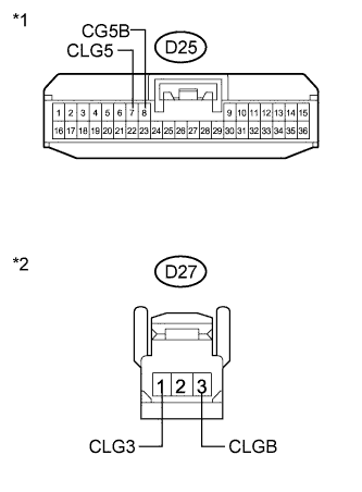
Text in Illustration *1 Front view of wire harness connector
(to Certification ECU (Smart Key ECU Assembly))
*2 Front view of wire harness connector
(to Indoor Electrical Key Oscillator (for Front Floor))
Disconnect the indoor electrical key oscillator (for front floor) connector.
-
Measure the resistance according to the value(s) in the table below.
Standard Resistance Tester Connection Condition Specified Condition D25-7 (CLG5) - D27-1 (CLG3) Always Below 1 Ω D25-8 (CG5B) - D27-3 (CLGB) Always Below 1 Ω D25-7 (CLG5) - Body ground Always 10 kΩ or higher D25-8 (CG5B) - Body ground Always 10 kΩ or higher D27-1 (CLG3) - Body ground Always 10 kΩ or higher D27-3 (CLGB) - Body ground Always 10 kΩ or higher
NG
REPAIR OR REPLACE HARNESS OR CONNECTOR
OK
-
-
INSPECT INDOOR ELECTRICAL KEY OSCILLATOR (for Front Floor (INPUT))
-
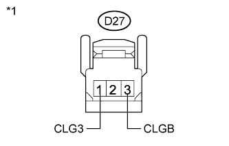
Text in Illustration *1 Front view of wire harness connector
(to Indoor Electrical Key Oscillator (for Front Floor))
Reconnect the certification ECU (smart key ECU assembly) connector.
-
Check for pulses according to the value(s) in the table below.
Standard Tester Connection Condition Specified Condition D27-1 (CLG3) - D27-3 (CLGB)
-
Engine switch off
-
All door closed
-
Key not in cabin
-
Door outside handle assembly (lock sensor) not touched
No pulse generation D27-1 (CLG3) - D27-3 (CLGB)
-
Engine switch off
-
All door closed
-
Key not in cabin
-
Door outside handle assembly (lock sensor) touched
Pulse generation -
NG
REPLACE CERTIFICATION ECU (SMART KEY ECU ASSEMBLY)
OK
-
-
REPLACE INDOOR ELECTRICAL KEY OSCILLATOR (for Front Floor)
-
Replace the indoor electrical key oscillator (for front floor Click here.
NEXT
-
-
CHECK SMART ENTRY AND START SYSTEM (ENTRY IGNITION FUNCTION (for Front Floor))
-
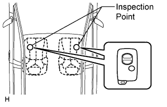
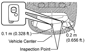
Inspect the detection area for the entry ignition function (for front floor). Make sure that the direction of the key is as shown in the illustration. When the key is in either of the 2 inspection points shown in the illustration, check that the engine can start.
OK Engine starts normally.
NG
REPLACE CERTIFICATION ECU (SMART KEY ECU ASSEMBLY)
OK
END (INDOOR ELECTRICAL KEY OSCILLATOR WAS DEFECTIVE)
-
-
CHECK HARNESS AND CONNECTOR (CERTIFICATION ECU - INDOOR ELECTRICAL KEY OSCILLATOR)
-
Disconnect the certification ECU (smart key ECU assembly) connector.
-
Text in Illustration *1 Front view of wire harness connector
(to Certification ECU (Smart Key ECU Assembly))
*2 Front view of wire harness connector
(to Indoor Electrical Key Oscillator (for Center Floor))
Disconnect the indoor electrical key oscillator (for center floor) connector.
-
Measure the resistance according to the value(s) in the table below.
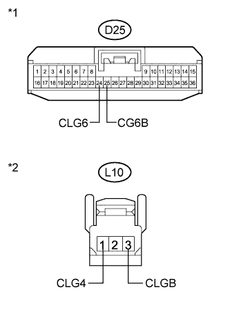
Standard Resistance Tester Connection Condition Specified Condition D25-24 (CLG6) - L10-1 (CLG4) Always Below 1 Ω D25-25 (CG6B) - L10-3 (CLGB) Always Below 1 Ω D25-24 (CLG6) - Body ground Always 10 kΩ or higher D25-25 (CG6B) - Body ground Always 10 kΩ or higher L10-1 (CLG4) - Body ground Always 10 kΩ or higher L10-3 (CLGB) - Body ground Always 10 kΩ or higher
NG
REPAIR OR REPLACE HARNESS OR CONNECTOR
OK
-
-
INSPECT INDOOR ELECTRICAL KEY OSCILLATOR (for Center Floor (INPUT))
-
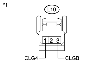
Text in Illustration *1 Front view of wire harness connector
(to Indoor Electrical Key Oscillator (for Center Floor))
Reconnect the certification ECU (smart key ECU assembly) connector.
-
Check for pulses according to the value(s) in the table below.
Standard Tester Connection Condition Specified Condition L10-1 (CLG4) - L10-3 (CLGB)
-
Engine switch off
-
All door closed
-
Key not in cabin
-
Door outside handle assembly (lock sensor) not touched
No pulse generation L10-1 (CLG4) - L10-3 (CLGB)
-
Engine switch off
-
All door closed
-
Key not in cabin
-
Door outside handle assembly (lock sensor) touched
Pulse generation -
NG
REPLACE CERTIFICATION ECU (SMART KEY ECU ASSEMBLY)
OK
-
-
REPLACE INDOOR ELECTRICAL KEY OSCILLATOR (for Center Floor)
-
Replace the indoor electrical key oscillator (for center floor) Click here.
NEXT
-
-
CHECK SMART ENTRY AND START SYSTEM (ENTRY IGNITION FUNCTION (for Center Floor))
-
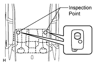
Inspect the detection area for the entry ignition function (for center floor). Make sure that the direction of the key is as shown in the illustration. When the key is in either of the 2 inspection points shown in the illustration, check that the engine can start.
OK Engine starts normally.
NG
REPLACE CERTIFICATION ECU (SMART KEY ECU ASSEMBLY)
OK
END (INDOOR ELECTRICAL KEY OSCILLATOR WAS DEFECTIVE)
-
-
CHECK HARNESS AND CONNECTOR (CERTIFICATION ECU - INDOOR ELECTRICAL KEY OSCILLATOR)
-
Disconnect the certification ECU (smart key ECU assembly) connector.
-
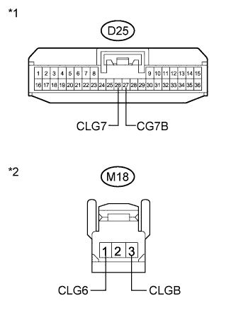
Text in Illustration *1 Front view of wire harness connector
(to Certification ECU (Smart Key ECU Assembly))
*2 Front view of wire harness connector
(to Indoor Electrical Key Oscillator (for Rear Floor))
Disconnect the indoor electrical key oscillator (for rear floor) connector.
-
Measure the resistance according to the value(s) in the table below.
Standard Resistance Tester Connection Condition Specified Condition D25-26 (CLG7) - M18-1 (CLG6) Always Below 1 Ω D25-27 (CG7B) - M18-3 (CLGB) Always Below 1 Ω D25-26 (CLG7) - Body ground Always 10 kΩ or higher D25-27 (CG7B) - Body ground Always 10 kΩ or higher M18-1 (CLG6) - Body ground Always 10 kΩ or higher M18-3 (CLGB) - Body ground Always 10 kΩ or higher
NG
REPAIR OR REPLACE HARNESS OR CONNECTOR
OK
-
-
INSPECT INDOOR ELECTRICAL KEY OSCILLATOR (for Rear Floor (INPUT))
-
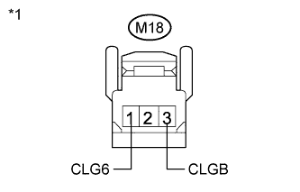
Text in Illustration *1 Front view of wire harness connector
(to Indoor Electrical Key Oscillator (for Rear Floor))
Reconnect the certification ECU (smart key ECU assembly) connector.
-
Check for pulses according to the value(s) in the table below.
Standard Tester Connection Condition Specified Condition M18-1 (CLG6) - M18-3 (CLGB)
-
Engine switch off
-
All door closed
-
Key not in cabin
-
Door outside handle assembly (lock sensor) not touched
No pulse generation M18-1 (CLG6) - M18-3 (CLGB)
-
Engine switch off
-
All door closed
-
Key not in cabin
-
Door outside handle assembly (lock sensor) touched
Pulse generation -
NG
REPLACE CERTIFICATION ECU (SMART KEY ECU ASSEMBLY)
OK
-
-
REPLACE INDOOR ELECTRICAL KEY OSCILLATOR (for Rear Floor)
-
Replace the indoor electrical key oscillator (fro rear floor) Click here.
NEXT
-
-
CHECK SMART ENTRY AND START SYSTEM (ENTRY IGNITION FUNCTION (for Rear Floor))
-
Inspect the detection area for the entry ignition function (for rear floor). Make sure that the direction of the key is as shown in the illustration. When the key is in either of the 2 inspection points shown in the illustration, check that the engine can start.
OK Engine starts normally.
NG
REPLACE CERTIFICATION ECU (SMART KEY ECU ASSEMBLY)
OK
END (INDOOR ELECTRICAL KEY OSCILLATOR WAS DEFECTIVE)
-
-
CHECK TRANSMITTER BATTERY
-

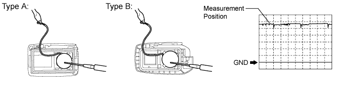
Text in Illustration *1 Type A *2 Type B Remove the battery from the key that does not operate. Attach a lead wire (0.6 mm (0.0236 in.) or less in diameter including wire sheath) with tape or equivalent to the negative (-) terminal Click here.
Note
Do not wrap a lead wire around the terminal, wedge it between the terminals, or solder it. Terminal may be deformed or damaged, and the battery will not be able to be installed correctly.
-
Carefully pull the lead wire out from the position shown in the illustration and install the previously removed transmitter battery.
-
Using an oscilloscope, check the transmitter battery voltage waveform.
Tech Tips
When measuring the battery voltage, while operating the lock switch of a door outside handle assembly, bring the key within the entry operating range to perform the measurement. For the entry operating range, refer to System Description Click here.
Standard Voltage Item Content Tester Connection Battery positive (+) - Battery negative (-) Tool Setting 0.5 V/DIV., 100 ms/DIV. Condition Engine switch off, all doors closed and lock switch pushed Specified Condition 2.2 to 3.2 V (Refer to the waveform)
NG
REPLACE TRANSMITTER BATTERY Click here
OK
-
-
CHECK ELECTRICAL KEY TRANSMITTER
-
Check if another registered key is available.
Result Result Proceed to Another registered key is not available. A Another registered key is available. B
B
CHECK ELECTRICAL KEY TRANSMITTER (OPERATION) Click here
A
-
-
REGISTER ELECTRICAL KEY TRANSMITTER
-
Register a new key.
Tech Tips
Refer to Service Bulletin.
NEXT
-
-
CHECK ELECTRICAL KEY TRANSMITTER (OPERATION)
-
Using the key registered in the previous step or another registered key, check that the engine starts normally.
OK Engine starts normally.
NG
REPLACE CERTIFICATION ECU (SMART KEY ECU ASSEMBLY)
OK
REPLACE ELECTRICAL KEY TRANSMITTER (REPLACE MALFUNCTIONING KEY)
-