SMART ENTRY AND START SYSTEM (for Entry Function) Front Passenger Side Door Entry Lock and Unlock Functions do not Operate
DESCRIPTION
When the entry lock and unlock functions do not operate only for the front passenger door, an error in output request codes from the front passenger door or malfunction in the front door outside handle assembly is suspected. If the entry functions for the other doors operate normally, then the communication circuit between the key and door control receiver assembly is functioning normally. In this case, radio wave interference or a malfunction in the request code sending circuit (from the certification ECU (smart key ECU assembly) to the front door outside handle assembly (for driver side)) is suspected.
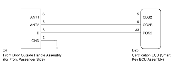
WIRING DIAGRAM
INSPECTION PROCEDURE
Note
-
The smart entry and start system (for entry function) uses a multiplex communication system (LIN communication system) and CAN communication system. Inspect the communication function by following How to Proceed with Troubleshooting Click here. Troubleshoot the smart entry and start system (for entry function) after confirming that the communication system is functioning properly.
-
Confirm that another key is not in the cabin.
-
Before replacing the certification ECU (smart key ECU assembly), refer to Service Bulletin.
PROCEDURE
-
CHECK POWER DOOR LOCK OPERATION
-
When the door control switch on the master switch assembly is operated, check that the doors unlock and lock according to switch operation Click here.
OK Door locks operate normally.
NG 
GO TO POWER DOOR LOCK CONTROL SYSTEM (Proceed to Problem Symptoms Table) Click here
OK 
-
-
CHECK WAVE ENVIRONMENT
-
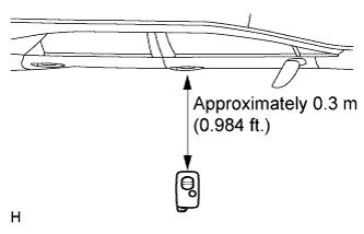
Bring the key near the front door outside handle assembly (for front passenger side), and perform a front passenger door entry lock and unlock operation check.
Note
If the key is brought within 0.2 m (0.656 ft.) of the door outside handle assembly, communication is not possible.
Tech Tips
-
When the key is brought near the front door outside handle assembly (for front passenger side), the possibility of wave interference decreases, and it can be determined if wave interference is causing the problem symptom.
-
If the operation is normal, the possibility of wave interference is high. Also, added vehicle components may cause wave interference. If installed, remove them and perform the operation check.
OK Entry functions operate normally. -
NG 
CHECK HARNESS AND CONNECTOR (CERTIFICATION ECU - FRONT DOOR OUTSIDE HANDLE) Click here
OK 
AFFECTED BY WAVE INTERFERENCE
-
-
CHECK HARNESS AND CONNECTOR (CERTIFICATION ECU - FRONT DOOR OUTSIDE HANDLE)
-
Disconnect the certification ECU (smart key ECU assembly) connector.
-
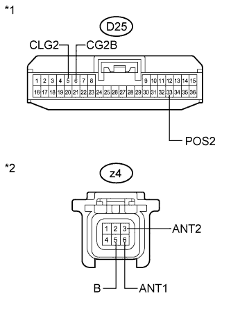
Text in Illustration *1 Front view of wire harness connector
(to Certification ECU (Smart Key ECU Assembly))
*2 Front view of wire harness connector
(to Front Door Outside Handle Assembly (for Front Passenger Side))
Disconnect the front door outside handle assembly (for front passenger side) connector.
-
Measure the resistance according to the value(s) in the table below.
Standard Resistance Tester Connection Condition Specified Condition D25-5 (CLG2) - z4-6 (ANT1) Always Below 1 Ω D25-6 (CG2B) - z4-3 (ANT2) Always Below 1 Ω D25-33 (POS2) - z4-5 (B) Always Below 1 Ω D25-5 (CLG2) - Body ground Always 10 kΩ or higher D25-6 (CG2B) - Body ground Always 10 kΩ or higher D25-33 (POS2) - Body ground Always 10 kΩ or higher z4-6 (ANT1) - Body ground Always 10 kΩ or higher z4-3 (ANT2) - Body ground Always 10 kΩ or higher z4-5 (B) - Body ground Always 10 kΩ or higher
NG
REPAIR OR REPLACE HARNESS OR CONNECTOR
OK
-
-
CHECK HARNESS AND CONNECTOR (FRONT DOOR OUTSIDE HANDLE - BODY GROUND)
-
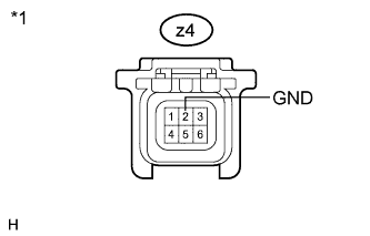
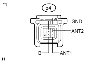
Text in Illustration *1 Front view of wire harness connector
(to Front Door Outside Handle Assembly (for Front Passenger Side))
Measure the resistance according to the value(s) in the table below.
Standard Resistance Tester Connection Condition Specified Condition z4-2 (GND) - Body ground Always Below 1 Ω
NG
REPAIR OR REPLACE HARNESS OR CONNECTOR
OK
-
-
INSPECT FRONT DOOR OUTSIDE HANDLE ASSEMBLY (DOOR OSCILLATOR, LOCK/UNLOCK SENSOR SIGNAL INPUT)
-
Reconnect the certification ECU (smart key ECU assembly) connector.
-
Text in Illustration *1 Front view of wire harness connector
(to Front Door Outside Handle Assembly (for Front Passenger Side))
Measure the voltage and check for pulses according to the value(s) in the table below.
Standard Tester Connection Condition Specified Condition z4-6 (ANT1) - z4-3 (ANT2)
-
Engine switch off
-
All door closed
-
Key not in cabin
No pulse generation z4-6 (ANT1) - z4-3 (ANT2)
-
Engine switch off
-
All door closed
-
Key not in cabin
-
All doors locked by wireless lock function
Pulse generation z4-5 (B) - z4-2 (GND) Engine switch off 9 to 14 V z4-5 (B) - z4-2 (GND) Engine switch on (IG) Below 2 V -
NG
REPLACE CERTIFICATION ECU (SMART KEY ECU ASSEMBLY)
OK
-
-
REPLACE FRONT DOOR OUTSIDE HANDLE ASSEMBLY (for Front Passenger Side)
-
Replace the front door outside handle assembly (for front passenger side) Click here.
NEXT
-
-
CHECK FRONT DOOR OUTSIDE HANDLE ASSEMBLY (for Front Passenger Side)
-
Check that the entry functions operate normally Click here.
OK Entry functions operate normally.
NG
REPLACE CERTIFICATION ECU (SMART KEY ECU ASSEMBLY)
OK
END (FRONT DOOR OUTSIDE HANDLE ASSEMBLY WAS DEFECTIVE)
-