SMART ENTRY AND START SYSTEM (for Entry Function), Diagnostic DTC:B27A1

| DTC Code | DTC Name |
|---|---|
| B27A1 | Open in Driver Side Electrical Antenna Circuit |
DESCRIPTION
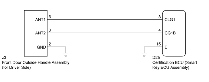
The certification ECU (smart key ECU assembly) generates a request signal and sends it to the door electrical key oscillator built into the front door outside handle assembly (for driver side) at 0.25-second intervals. To detect a key near the driver door, the front door outside handle assembly (for driver side) creates a detection area with a radius of approximately 1.0 m (3.28 ft.) from the driver door at 0.25-second intervals.
DTC B27A1 is detected by the certification ECU (smart key ECU assembly) if an open circuit is detected between the certification ECU (smart key ECU assembly) and front door outside handle assembly (for driver side) terminals (between CLG1 and ANT1, or CG1B and ANT2).
| DTC No. | DTC Detection Condition | Trouble Area |
|---|---|---|
| B27A1 | Open circuit detected between the certification ECU (smart key ECU assembly) and front door outside handle assembly (for driver side) terminals (between CLG1 and ANT1, or CG1B and ANT2). |
|
WIRING DIAGRAM
INSPECTION PROCEDURE
Note
-
The smart entry and start system (for entry function) uses a multiplex communication system (LIN communication system) and CAN communication system. Inspect the communication function by following How to Proceed with Troubleshooting Click here. Troubleshoot the smart entry and start system (for entry function) after confirming that the communication system is functioning properly.
-
Before replacing the certification ECU (smart key ECU assembly), refer to Service Bulletin.
PROCEDURE
-
CHECK CONNECTOR (CONNECTOR CONNECTION CONDITION)
-
Turn the engine switch off.
-
Check that the connectors are properly connected to the certification ECU (smart key ECU assembly) and the front door outside handle assembly (for driver side).
OK Connectors are properly connected.
NG 
CONNECT CONNECTORS PROPERLY
OK 
-
-
CHECK HARNESS AND CONNECTOR (CERTIFICATION ECU - FRONT DOOR OUTSIDE HANDLE)
-
Disconnect the certification ECU (smart key ECU assembly) connector.
-
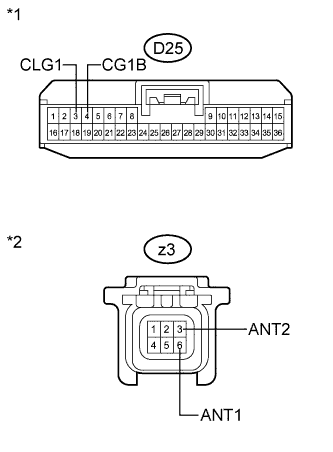
Text in Illustration *1 Front view of wire harness connector
(to Certification ECU (Smart Key ECU Assembly))
*2 Front view of wire harness connector
(to Front Door Outside Handle Assembly (for Driver Side))
Disconnect the front door outside handle assembly (for driver side) connector.
-
Measure the resistance according to the value(s) in the table below.
Standard Resistance Tester Connection Condition Specified Condition D25-3 (CLG1) - z3-6 (ANT1) Always Below 1 Ω D25-4 (CG1B) - z3-3 (ANT2) Always Below 1 Ω D25-3 (CLG1) - Body ground Always 10 kΩ or higher D25-4 (CG1B) - Body ground Always 10 kΩ or higher z3-6 (ANT1) - Body ground Always 10 kΩ or higher z3-3 (ANT2) - Body ground Always 10 kΩ or higher
NG
REPAIR OR REPLACE HARNESS OR CONNECTOR
OK
-
-
CHECK HARNESS AND CONNECTOR (FRONT DOOR OUTSIDE HANDLE - BODY GROUND)
-
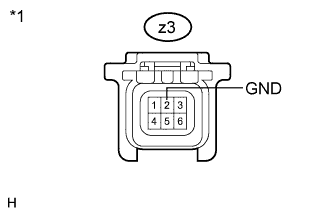
Text in Illustration *1 Front view of wire harness connector
(to Front Door Outside Handle Assembly (for Driver Side))
Measure the resistance according to the value(s) in the table below.
Standard Resistance Tester Connection Condition Specified Condition z3-2 (GND) - Body ground Always Below 1 Ω
NG
REPAIR OR REPLACE HARNESS OR CONNECTOR
OK
-
-
INSPECT CERTIFICATION ECU (SMART KEY ECU ASSEMBLY) (INDOOR ELECTRICAL KEY OSCILLATOR SIGNAL OUTPUT)
-
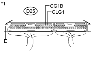
Text in Illustration *1 Component with harness connected
(Certification ECU (Smart Key ECU Assembly))
Reconnect the certification ECU (smart key ECU assembly) connector.
-
Measure the resistance and check for pulses according to the value(s) in the table below.
Standard Resistance Tester Connection Condition Specified Condition D25-15 (E) - Body ground Always Below 1 Ω Standard Tester Connection Condition Specified Condition D25-3 (CLG1) - D25-15 (E)
-
Engine switch off
-
All door closed
-
Key not in cabin
No pulse generation D25-3 (CLG1) - D25-15 (E)
-
Engine switch off
-
All door closed
-
Key not in cabin
-
All doors locked by wireless lock function
Pulse generation D25-4 (CG1B) - D25-15 (E)
-
Engine switch off
-
All door closed
-
Key not in cabin
No pulse generation D25-4 (CG1B) - D25-15 (E)
-
Engine switch off
-
All door closed
-
Key not in cabin
-
All doors locked by wireless lock function
Pulse generation -
NG
REPLACE CERTIFICATION ECU (SMART KEY ECU ASSEMBLY)
OK
-
-
REPLACE FRONT DOOR OUTSIDE HANDLE ASSEMBLY (for Driver Side)
-
Replace the front door outside handle assembly (for driver side) Click here.
NEXT
-
-
CHECK DTC OUTPUT
-
Clear the DTCs Click here.
-
Recheck for DTCs.
OK DTC B27A1 is not output.
NG
REPLACE CERTIFICATION ECU (SMART KEY ECU ASSEMBLY)
OK 
END (FRONT DOOR OUTSIDE HANDLE ASSEMBLY WAS DEFECTIVE)
-