KEY REMINDER WARNING SYSTEM TERMINALS OF ECU

-
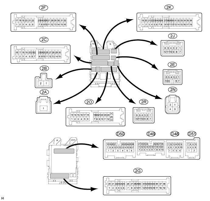
CHECK MAIN BODY ECU (DRIVER SIDE JUNCTION BLOCK ASSEMBLY)
-
Disconnect the 2F and 2C driver side junction block connectors.
-
Disconnect the D50 and D51 main body ECU connectors.
-
Measure the resistance and voltage according to the value(s) in the table below.
Tech Tips
Measure the values on the wire harness side with the connector disconnected.
Tester Connection Wiring Color Terminal Description Condition Specified Condition 2F-16 (GND1) - Body ground W-B - Body ground Ground Always Below 1 Ω 2C-30 (ALTB) - Body ground BR - Body ground Battery power supply Always 11 to 14 V D50-24 (DCTY) - Body ground V - Body ground Driver door courtesy light switch signal Switch pushed (Door closed) 10 kΩ or higher D50-24 (DCTY) - Body ground V - Body ground Driver door courtesy light switch signal Switch free (Door open) Below 1 Ω D51-5 (KSW) - Body ground L - Body ground Unlock warning switch signal No key is in ignition key cylinder 10 kΩ or higher D51-5 (KSW) - Body ground L - Body ground Unlock warning switch signal Key is in ignition key cylinder Below 1 Ω If the result is not as specified, there may be a malfunction on the wire harness side.
-