WIRELESS DOOR LOCK CONTROL SYSTEM (w/o Smart Entry and Start System), Diagnostic DTC:B1242

| DTC Code | DTC Name |
|---|---|
| B1242 | Wireless Door Lock Tuner Circuit Malfunction |
DESCRIPTION
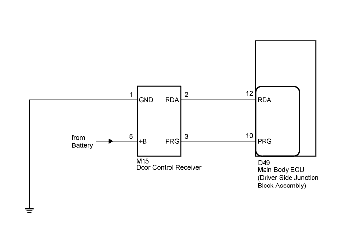
The door control receiver receives signals from the transmitter and sends these signals to the main body ECU (driver side junction block assembly).
| DTC No. | DTC Detection Condition | Trouble Area |
|---|---|---|
| B1242 | In diagnostic mode, an applicable RDA signal cannot be received within 2.4 seconds after a PRG signal has been output from the main body ECU (driver side junction block assembly). |
|
WIRING DIAGRAM
INSPECTION PROCEDURE
PROCEDURE
-
CHECK HARNESS AND CONNECTOR (MAIN BODY ECU - DOOR CONTROL RECEIVER)
-
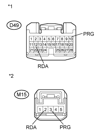
Text in Illustration *1 Front view of wire harness connector
(to Main Body ECU (Driver Side Junction Block Assembly))
*2 Front view of wire harness connector
(to Door Control Receiver)
Disconnect the D49 main body ECU (driver side junction block assembly) connector.
-
Disconnect the M15 door control receiver connector.
-
Measure the resistance according to the value(s) in the table below.
Standard Resistance Tester Connection Condition Specified Condition D49-12 (RDA) - M15-2 (RDA) Always Below 1 Ω D49-12 (RDA) - Body ground Always 10 kΩ or higher D49-10 (PRG) - M15-3 (PRG) Always Below 1 Ω D49-10 (PRG) - Body ground Always 10 kΩ or higher
NG 
REPAIR OR REPLACE HARNESS OR CONNECTOR
OK 
-
-
CHECK HARNESS AND CONNECTOR (BATTERY, BODY GROUND)
-
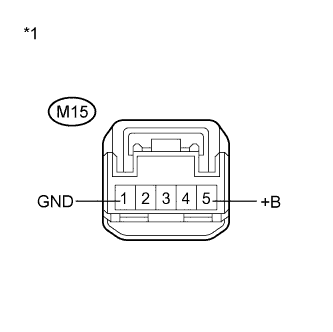
Text in Illustration *1 Front view of wire harness connector
(to Door Control Receiver)
Measure the resistance according to the value(s) in the table below.
Standard Resistance Tester Connection Condition Specified Condition M15-1 (GND) - Body ground Always Below 1 Ω -
Measure the voltage according to the value(s) in the table below.
Standard Voltage Tester Connection Condition Specified Condition M15-5 (+B) - Body ground Always 11 to 14 V
NG
REPAIR OR REPLACE HARNESS OR CONNECTOR
OK
-
-
REPLACE DOOR CONTROL RECEIVER
-
Temporarily replace the door lock control receiver with a new one Click here.
NEXT
-
-
REGISTER RECOGNITION CODE
-
Perform the Registration procedure Click here.
NEXT
-
-
CHECK FOR DTC
-
Clear the DTCs Click here.
-
Recheck for DTCs.
OK DTC B1242 is not output.
NG
REPLACE MAIN BODY ECU (DRIVER SIDE JUNCTION BLOCK ASSEMBLY) Click here
OK 
END (DOOR CONTROL RECEIVER WAS DEFECTIVE)
-