WIRELESS DOOR LOCK CONTROL SYSTEM (w/ Smart Entry and Start System) TERMINALS OF ECU

-
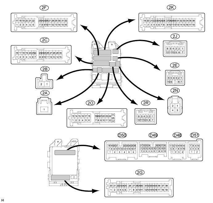
CHECK MAIN BODY ECU (DRIVER SIDE JUNCTION BLOCK ASSEMBLY)
-
Disconnect the 2A, 2C and 2F main body ECU (driver side junction block assembly) connectors.
-
Measure the voltage and resistance according to the value(s) in the table below.
Tech Tips
Measure the values on the wire harness side with the connector disconnected.
Symbols (Terminal No.) Wiring Color Terminal Description Condition Specified Condition 2A-1 (IG) - Body ground B - Body ground Ignition power supply (IG signal) Engine switch on (IG) → off 10 to 14 V → Below 1 V 2A-1 (ACC) - Body ground B - Body ground Ignition power supply (ACC signal) Engine switch on (ACC) → off 10 to 14 V → Below 1 V 2C-30 (ALTB) - Body ground BR - Body ground +B (power system alternator system) power supply Always 10 to 14 V 2F-16 (GND1) - Body ground W-B - Body ground Ground Always Below 1 Ω If the result is not as specified, there may be a malfunction on the wire harness side.
-
Reconnect the 2A, 2C and 2F main body ECU (driver side junction block assembly) connectors.
-
Measure the voltage according to the value(s) in the table below.
Symbols (Terminal No.) Wiring Color Terminal Description Condition Specified Condition D50-24 (DCTY) - Body ground V - Body ground Driver side door courtesy light switch input Driver side door CLOSED (OFF) → OPEN (ON) Pulse generation → Below 1 V D49-21 (PCTY) - Body ground V - Body ground Passenger side courtesy light switch input Passenger side door CLOSED (OFF) → OPEN (ON) Pulse generation → Below 1 V D49-7 (RCTY) - Body ground GR - Body ground Rear courtesy light switch RH input Rear door RH CLOSED (OFF) → OPEN (ON) Pulse generation → Below 1 V 2O-19 (LCTY) - Body ground R - Body ground Rear courtesy light switch LH input Rear door LH CLOSED (OFF) → OPEN (ON) Pulse generation → Below 1 V D49-25 (BCTY) - Body ground GR - Body ground Back door courtesy light switch input Back door CLOSED (OFF) → OPEN (ON) Pulse generation → Below 1 V D48-4 (HAZ) - Body ground G - Body ground Turn signal flasher relay signal Any transmitter switch is pressed → not pressed Below 1 V → 10 to 14 V D51-7 (BZR) - Body ground LG - Body ground Wireless door lock buzzer signal Wireless door lock buzzer OFF → ON Below 1 V → Pulse generation If the result is not as specified, the main body ECU (driver side junction block assembly) may be malfunctioning.
-
-
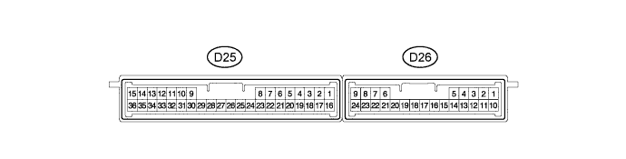
CHECK CERTIFICATION ECU (SMART KEY ECU ASSEMBLY)
-
Disconnect the D25 and D26 certification ECU (smart key ECU assembly) connectors.
-
Measure the resistance and voltage according to the value(s) in the table below.
Terminal No. (Symbols) Wiring Color Terminal Description Condition Specified Condition D25-15 (E) - Body ground B - Body ground Ground Always Below 1 Ω D25-1 (+B) - D25-15 (E) G - B Battery power supply Always 11 to 14 V D25-16 (IG) - D25-15 (E) R - B IG power supply Engine switch on (IG) 11 to 14 V Engine switch off Below 1 V
-
If the result is not as specified, there may be a malfunction on the wire harness side.
-
-
Reconnect the D25 and D26 certification ECU (smart key ECU assembly) connectors.
-
Measure the voltage according to the value(s) in the table below.
Terminal No. (Symbols) Wiring Color Terminal Description Condition Specified Condition D26-16 (RSSI) - D25-15 (E) P - B Door control receiver output signal Engine switch off, all doors closed and transmitter switch not pressed 11 to 14 V Engine switch off, all doors closed and transmitter switch pressed Below 2 V D26-15 (RDA) - D25-15 (E) R - B Door control receiver input signal Engine switch off, all doors closed and transmitter switch not pressed 11 to 14 V pulse generation at regular intervals Engine switch off, all doors closed and transmitter switch pressed Pulse generation D26-5 (RCO) - D25-15 (E) Y - B Supply battery to door control receiver Engine switch off, all doors closed and transmitter switch pressed 4.5 to 5.5 V
-
If the result is not as specified, the certification ECU (smart key ECU assembly) may be malfunctioning.
-
-