CAN COMMUNICATION SYSTEM, Diagnostic DTC:U1002

| DTC Code | DTC Name |
|---|---|
| U1002 | Lost Communication with Gateway Module (MS Bus) |
DESCRIPTION
-
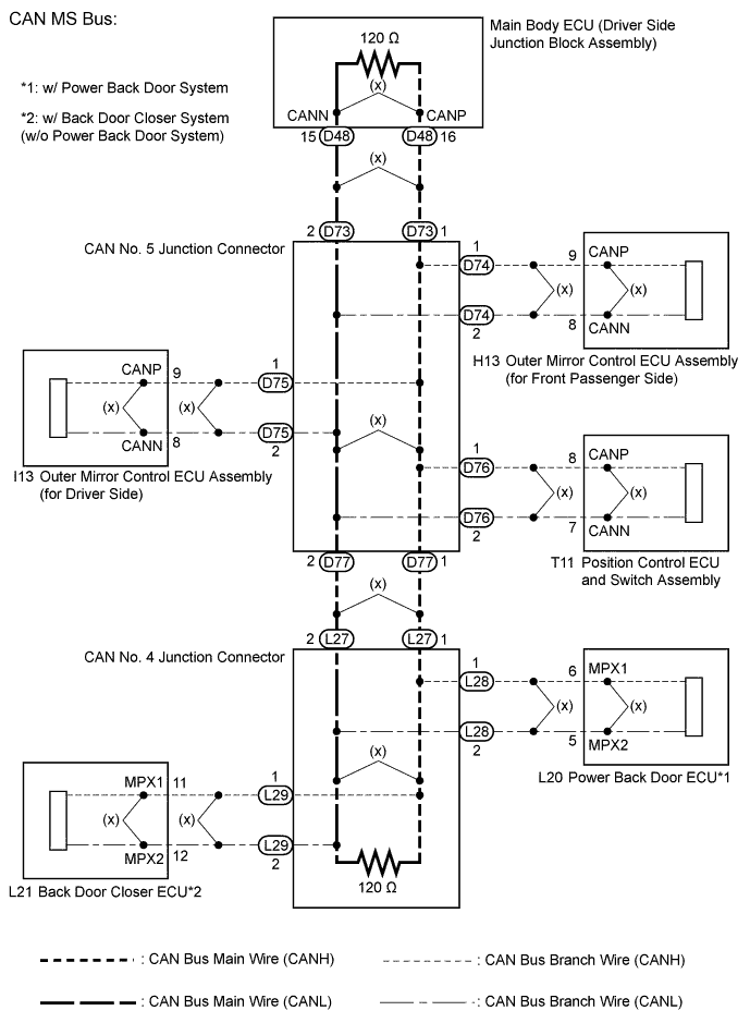
The main body ECU (driver side junction block assembly) will store this DTC when no signals can be received from the ECUs that have been memorized as those that are connected to the CAN MS bus.
-
When the main body ECU (driver side junction block assembly) receives a response signal from the ECUs connected to the CAN MS bus, the main body ECU (driver side junction block assembly) recognizes and memorizes that the ECU is connected to the CAN MS bus. Based on this memorized data, the main body ECU (driver side junction block assembly) monitors for malfunctions in the ECUs connected to the CAN MS bus when communicating with those ECUs. If the main body ECU (driver side junction block assembly) cannot receive response signals from the ECUs that have been memorized as those connected to the CAN MS bus, the main body ECU (driver side junction block assembly) determines that a malfunction exists.
| DTC No. | DTC Detection Condition | Trouble Area |
|---|---|---|
| U1002 | Main body ECU (driver side junction block assembly) cannot receive signals from all ECUs that have been memorized as those connected to the CAN MS bus. |
|
-
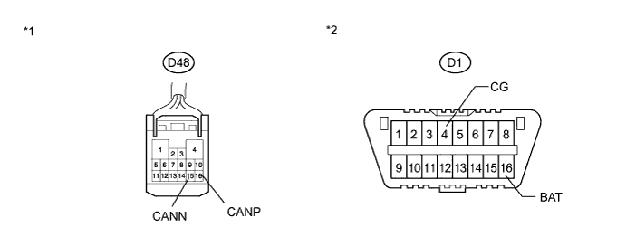
*1: w/ Power back door system
-
*2: w/ Back door closer system (w/o power back door system)
WIRING DIAGRAM
INSPECTION PROCEDURE
Note
-
Turn the ignition switch off before measuring the resistances between CAN bus main wires and between CAN bus branch wires.
-
Turn the ignition switch off before inspecting CAN bus wires for a ground short.
-
After the ignition switch is turned off, check that the key reminder warning system and light reminder warning system are not operating.
-
Before measuring the resistance, leave the vehicle as is for at least 1 minute and do not operate the ignition switch, any other switches or the doors. If any doors need to be opened in order to check connectors, open the doors and leave them open.
Tech Tips
-
Operating the ignition switch, any other switches or a door triggers related ECU and sensor communication on the CAN. This communication will cause the resistance value to change.
-
Even after DTCs are cleared, if a DTC is stored again after driving the vehicle for a while, the malfunction may be occurring due to vibration of the vehicle. In such a case, wiggling the ECUs or wire harness while performing the inspection below may help determine the cause of the malfunction.
PROCEDURE
-
CHECK CAN MS BUS WIRE
-
Turn the ignition switch off.
-
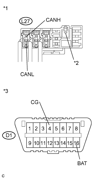
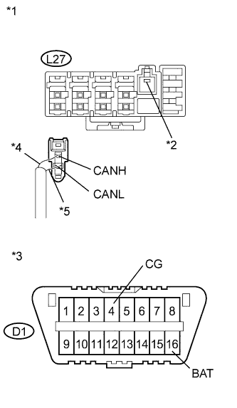
Text in Illustration *1 Component with harness connected
(CAN No. 4 Junction Connector)
*2 Earth Terminal *3 DLC3 Measure the resistance according to the value(s) in the table below.
Standard Resistance Tester Connection Condition Specified Condition Result L27-1 (CANH) - L27-2 (CANL) Ignition switch off 54 to 69 Ω Below 54 Ω:
Short circuit between bus lines
70 Ω or more:
Open circuit in a main bus line
L27-1 (CANH) - D1-4 (CG) Ignition switch off 200 Ω or higher Below 200 Ω:
CANH ground short
L27-2 (CANL) - D1-4 (CG) Ignition switch off 200 Ω or higher Below 200 Ω:
CANL ground short
-
Disconnect the cable from the negative (-) battery terminal.
-
Measure the resistance according to the value(s) in the table below.
Standard Resistance Tester Connection Condition Specified Condition Result L27-1 (CANH) - D1-16 (BAT) Cable disconnected from negative (-) battery terminal 6 kΩ or higher Below 6 kΩ:
CANH +B short
L27-2 (CANL) - D1-16 (BAT) Cable disconnected from negative (-) battery terminal 6 kΩ or higher Below 6 kΩ:
CANL +B short
Result Result Proceed to OK A Open in CAN main bus line B
-
Short circuit between bus lines
-
Ground short
-
+B short
C -
B 
CHECK FOR OPEN IN CAN MS BUS MAIN WIRE (CAN NO. 4 J/C - CAN NO. 5 J/C) Click here
C
CHECK FOR SHORT IN CAN BUS WIRE (CAN NO. 4 J/C) Click here
A 
REPLACE MAIN BODY ECU (DRIVER SIDE JUNCTION BLOCK ASSEMBLY) Click here
-
-
CHECK FOR OPEN IN CAN MS BUS MAIN WIRE (CAN NO. 4 J/C - CAN NO. 5 J/C)
-
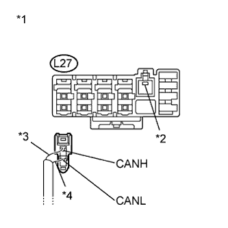
Text in Illustration *1 Rear view of wire harness connector
(to CAN No. 4 Junction Connector)
*2 Earth Terminal *3 Red *4 White Disconnect the CAN No. 4 junction connector (L27).
-
Measure the resistance according to the value(s) in the table below.
Standard Resistance Tester Connection Condition Specified Condition L27-1 (CANH) - L27-2 (CANL) Ignition switch off 108 to 132 Ω
NG
CHECK FOR OPEN IN CAN MS BUS MAIN WIRE (CAN NO. 5 J/C - CAN NO. 4 J/C) Click here
OK
REPLACE CAN NO. 4 J/C
-
-
CHECK FOR OPEN IN CAN MS BUS MAIN WIRE (CAN NO. 5 J/C - CAN NO. 4 J/C)
-
Reconnect the CAN No. 4 junction connector (L27).
-
Disconnect the CAN No. 5 junction connector (D77).
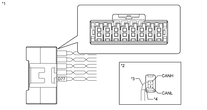
Text in Illustration *1 CAN No. 5 Junction Connector *2 Rear view of wire harness connector (to CAN No. 5 Junction Connector) *3 Red *4 White -
Measure the resistance according to the value(s) in the table below.
Standard Resistance Tester Connection Condition Specified Condition D77-1 (CANH) - D77-2 (CANL) Ignition switch off 108 to 132 Ω
NG 
REPAIR OR REPLACE CAN MS BUS MAIN WIRE OR CONNECTOR (CAN NO. 5 J/C - CAN NO. 4 J/C)
OK 
-
-
CHECK FOR OPEN IN CAN MS BUS MAIN WIRE (CAN NO. 5 J/C - MAIN BODY ECU (DRIVER SIDE JUNCTION BLOCK ASSEMBLY))
-
Reconnect the CAN No. 5 junction connector (D77).
-
Disconnect the CAN No. 5 junction connector (D73).
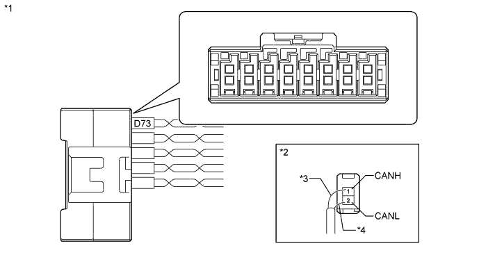
Text in Illustration *1 CAN No. 5 Junction Connector *2 Rear view of wire harness connector (to CAN No. 5 Junction Connector) *3 Sky Blue *4 White -
Measure the resistance according to the value(s) in the table below.
Standard Resistance Tester Connection Condition Specified Condition D73-1 (CANH) - D73-2 (CANL) Ignition switch off 108 to 132 Ω
NG
CHECK FOR OPEN IN CAN MS BUS MAIN WIRE (MAIN BODY ECU (DRIVER SIDE JUNCTION BLOCK ASSEMBLY) - CAN NO. 5 J/C) Click here
OK
REPLACE CAN NO. 5 J/C
-
-
CHECK FOR OPEN IN CAN MS BUS MAIN WIRE (MAIN BODY ECU (DRIVER SIDE JUNCTION BLOCK ASSEMBLY) - CAN NO. 5 J/C)
-
Reconnect the No. 5 junction connector (D73).
-
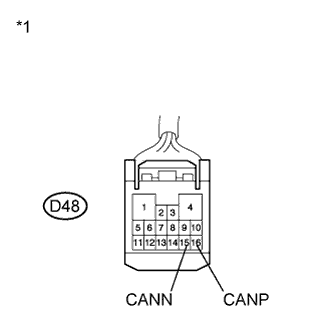
Text in Illustration *1 Front view of wire harness connector:
(to Main Body ECU (Driver Side Junction Block Assembly))
Disconnect the main body ECU (driver side junction block assembly) connector (D48).
-
Measure the resistance according to the value(s) in the table below.
Standard Resistance Tester Connection Condition Specified Condition D48-16 (CANP) - D48-15 (CANN) Ignition switch off 108 to 132 Ω
NG
REPAIR OR REPLACE CAN MS BUS MAIN WIRE OR CONNECTOR (MAIN BODY ECU (DRIVER SIDE JUNCTION BLOCK ASSEMBLY) - CAN NO. 5 J/C)
OK
REPLACE MAIN BODY ECU (DRIVER SIDE JUNCTION BLOCK ASSEMBLY) Click here
-
-
CHECK FOR SHORT IN CAN BUS WIRE (CAN NO. 4 J/C)
-
Turn the ignition switch off.
-
Text in Illustration *1 Rear view of wire harness connector
(to CAN No. 4 Junction Connector)
*2 Earth Terminal *3 DLC3 *4 Red *5 White Disconnect the CAN No. 4 junction connector (L27).
-
Measure the resistance according to the value(s) in the table below.
Standard Resistance Tester Connection Condition Specified Condition Purpose L27-1 (CANH) - L27-2 (CANL) Ignition switch off 108 to 132 Ω Inspection for open or short circuit between bus line L27-1 (CANH) - D1-4 (CG) Ignition switch off 200 Ω or higher Inspection for CANH ground short L27-2 (CANL) - D1-4 (CG) Ignition switch off 200 Ω or higher Inspection for CANL ground short L27-1 (CANH) - D1-16 (BAT) Cable disconnected from negative (-) battery terminal 6 kΩ or higher Inspection for CANH +B short L27-2 (CANL) - D1-16 (BAT) Cable disconnected from negative (-) battery terminal 6 kΩ or higher Inspection for CANL +B short Tech Tips
It is only necessary to perform the inspection in the above table for the result (open or short circuit) that was obtained in the Check CAN MS Bus Wire inspection.
Find the necessary inspection from the Purpose column that matches the result in the Result column from the Check CAN MS Bus Wire inspection.
Result Result Proceed to OK (w/ Power back door system) A OK (w/ Back door closer system) B NG C
B
CHECK FOR SHORT IN CAN MS BUS WIRES (BACK DOOR CLOSER ECU - CAN NO. 4 J/C) Click here
C
CHECK FOR SHORT IN CAN MS BUS WIRES (CAN NO. 5 J/C - CAN NO. 4 J/C) Click here
A
-
-
CHECK FOR SHORT IN CAN MS BUS WIRES (POWER BACK DOOR ECU - CAN NO. 4 J/C)
-
Reconnect the CAN No. 4 junction connector (L27).
-
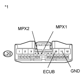
Text in Illustration *1 Front view of wire harness connector
(to Power Back Door ECU)
Disconnect the power back door ECU connector.
-
Measure the resistance according to the value(s) in the table below.
Standard Resistance Tester Connection Condition Specified Condition Purpose L20-6 (MPX1) - L20-5 (MPX2) Ignition switch off 54 to 69 Ω Inspection for open or short circuit between bus lines L20-6 (MPX1) - L20-11 (GND) Ignition switch off 200 Ω or higher Inspection for CANH ground short L20-5 (MPX2) - L20-11 (GND) Ignition switch off 200 Ω or higher Inspection for CANL ground short L20-6 (MPX1) - L20-10 (ECUB) Cable disconnected from negative (-) battery terminal 6 kΩ or higher Inspection for CANH +B short L20-5 (MPX2) - L20-10 (ECUB) Cable disconnected from negative (-) battery terminal 6 kΩ or higher Inspection for CANL +B short Tech Tips
It is only necessary to perform the inspection in the above table for the result (open or short circuit) that was obtained in the Check CAN MS Bus Wire inspection.
Find the necessary inspection from the Purpose column that matches the result in the Result column from the Check CAN MS Bus Wire inspection.
NG
CHECK CAN MS BUS BRANCH WIRE (POWER BACK DOOR ECU) Click here
OK
REPLACE POWER BACK DOOR ECU (BACK DOOR MOTOR UNIT) Click here
-
-
CHECK CAN MS BUS BRANCH WIRE (POWER BACK DOOR ECU)
-
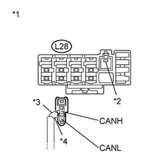
Text in Illustration *1 Rear view of wire harness connector
(to CAN No. 4 Junction Connector)
*2 Earth Terminal *3 Pink *4 White Disconnect the CAN No. 4 junction connector (L28).
-

Text in Illustration *5 Front view of wire harness connector:
(to Power Back Door ECU)
Measure the resistance according to the value(s) in the table below.
Standard Resistance Tester Connection Condition Specified Condition Purpose L20-6 (MPX1) - L20-5 (MPX2) Ignition switch off 1 MΩ or higher Inspection for open or short circuit between bus lines L20-6 (MPX1) - L20-11 (GND) Ignition switch off 200 Ω or higher Inspection for CANH ground short L20-5 (MPX2) - L20-11 (GND) Ignition switch off 200 Ω or higher Inspection for CANL ground short L20-6 (MPX1) - L20-10 (ECUB) Cable disconnected from negative (-) battery terminal 6 kΩ or higher Inspection for CANH +B short L20-5 (MPX2) - L20-10 (ECUB) Cable disconnected from negative (-) battery terminal 6 kΩ or higher Inspection for CANL +B short Tech Tips
It is only necessary to perform the inspection in the above table for the result (open or short circuit) that was obtained in the Check CAN MS Bus Wire inspection.
Find the necessary inspection from the Purpose column that matches the result in the Result column from the Check CAN MS Bus Wire inspection.
NG
REPAIR OR REPLACE CAN MS BUS BRANCH WIRE OR CONNECTOR (POWER BACK DOOR ECU)
OK
REPLACE CAN NO. 4 J/C
-
-
CHECK FOR SHORT IN CAN MS BUS WIRES (BACK DOOR CLOSER ECU - CAN NO. 4 J/C)
-
Reconnect the CAN No. 4 junction connector (L27).
-
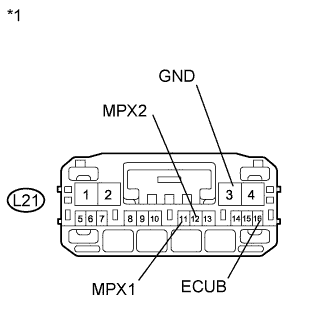
Text in Illustration *1 Front view of wire harness connector
(to Back Door Closer ECU)
Disconnect the back door closer ECU connector.
-
Measure the resistance according to the value(s) in the table below.
Standard Resistance Tester Connection Condition Specified Condition Purpose L21-11 (MPX1) - L21-12 (MPX2) Ignition switch off 54 to 69 Ω Inspection for open or short circuit between bus lines L21-11 (MPX1) - L21-3 (GND) Ignition switch off 200 Ω or higher Inspection for CANH ground short L21-12 (MPX2) - L21-3 (GND) Ignition switch off 200 Ω or higher Inspection for CANL ground short L21-11 (MPX1) - L21-16 (ECUB) Cable disconnected from negative (-) battery terminal 6 kΩ or higher Inspection for CANH +B short L21-12 (MPX2) - L21-16 (ECUB) Cable disconnected from negative (-) battery terminal 6 kΩ or higher Inspection for CANL +B short Tech Tips
It is only necessary to perform the inspection in the above table for the result (open or short circuit) that was obtained in the Check CAN MS Bus Wire inspection.
Find the necessary inspection from the Purpose column that matches the result in the Result column from the Check CAN MS Bus Wire inspection.
NG
CHECK CAN MS BUS BRANCH WIRE (BACK DOOR CLOSER ECU) Click here
OK
REPLACE BACK DOOR CLOSER ECU
-
-
CHECK CAN MS BUS BRANCH WIRE (BACK DOOR CLOSER ECU)
-
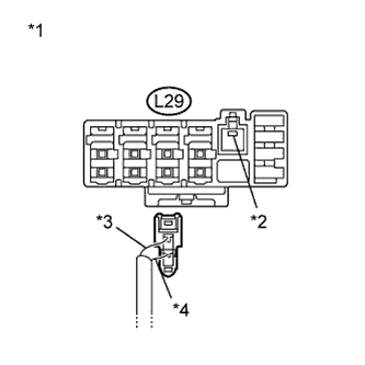
Text in Illustration *1 Rear view of wire harness connector
(to CAN No. 4 Junction Connector)
*2 Earth Terminal *3 Pink *4 White Disconnect the CAN No. 4 junction connector (L29).
-
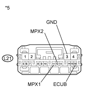
Text in Illustration *5 Front view of wire harness connector
(to Back Door Closer ECU)
Measure the resistance according to the value(s) in the table below.
Standard Resistance Tester Connection Condition Specified Condition Purpose L21-11 (MPX1) - L21-12 (MPX2) Ignition switch off 1 MΩ or higher Inspection for open or short circuit between bus lines L21-11 (MPX1) - L21-3 (GND) Ignition switch off 200 Ω or higher Inspection for CANH ground short L21-12 (MPX2) - L21-3 (GND) Ignition switch off 200 Ω or higher Inspection for CANL ground short L21-11 (MPX1) - L21-16 (ECUB) Cable disconnected from negative (-) battery terminal 6 kΩ or higher Inspection for CANH +B short L21-12 (MPX2) - L21-16 (ECUB) Cable disconnected from negative (-) battery terminal 6 kΩ or higher Inspection for CANL +B short Tech Tips
It is only necessary to perform the inspection in the above table for the result (open or short circuit) that was obtained in the Check CAN MS Bus Wire inspection.
Find the necessary inspection from the Purpose column that matches the result in the Result column from the Check CAN MS Bus Wire inspection.
NG
REPAIR OR REPLACE CAN MS BUS BRANCH WIRE OR CONNECTOR (BACK DOOR CLOSER ECU)
OK
REPLACE CAN NO. 4 J/C
-
-
CHECK FOR SHORT IN CAN MS BUS WIRES (CAN NO. 5 J/C - CAN NO. 4 J/C)
-
Reconnect the CAN No. 4 junction connector (L27).
-
Disconnect the CAN No. 5 junction connector (D77).

Text in Illustration *1 CAN No. 5 Junction Connector *2 Rear view of wire harness connector (to CAN No. 5 Junction Connector) *3 DLC3 *4 Red *5 White -
Measure the resistance according to the value(s) in the table below.
Standard Resistance Tester Connection Condition Specified Condition Purpose D77-1 (CANH) - D77-2 (CANL) Ignition switch off 108 to 132 Ω Inspection for open or short circuit between bus line D77-1 (CANH) - D1-4 (CG) Ignition switch off 200 Ω or higher Inspection for CANH ground short D77-2 (CANL) - D1-4 (CG) Ignition switch off 200 Ω or higher Inspection for CANL ground short D77-1 (CANH) - D1-16 (BAT) Cable disconnected from negative (-) battery terminal 6 kΩ or higher Inspection for CANH +B short D77-2 (CANL) - D1-16 (BAT) Cable disconnected from negative (-) battery terminal 6 kΩ or higher Inspection for CANL +B short Tech Tips
It is only necessary to perform the inspection in the above table for the result (open or short circuit) that was obtained in the Check CAN MS Bus Wire inspection.
Find the necessary inspection from the Purpose column that matches the result in the Result column from the Check CAN MS Bus Wire inspection.
NG
REPAIR OR REPLACE CAN MS BUS MAIN WIRE OR CONNECTOR (CAN NO. 5 J/C - CAN NO. 4 J/C)
OK
-
-
CHECK FOR SHORT IN CAN MS BUS WIRES (CAN NO. 5 J/C - POSITION CONTROL ECU AND SWITCH ASSEMBLY)
-
Disconnect the CAN No. 5 junction connector (D76).
-
Reconnect the CAN No. 5 junction connector (D77).

Text in Illustration *1 CAN No. 5 Junction Connector *2 Rear view of wire harness connector (to CAN No. 5 Junction Connector) *3 DLC3 *4 Green *5 Red -
Measure the resistance according to the value(s) in the table below.
Standard Resistance Tester Connection Condition Specified Condition Purpose D76-1 (CANH) - D76-2 (CANL) Ignition switch off 200 Ω or higher Inspection for open or short circuit between bus line D76-1 (CANH) - D1-4 (CG) Ignition switch off 200 Ω or higher Inspection for CANH ground short D76-2 (CANL) - D1-4 (CG) Ignition switch off 200 Ω or higher Inspection for CANL ground short D76-1 (CANH) - D1-16 (BAT) Cable disconnected from negative (-) battery terminal 6 kΩ or higher Inspection for CANH +B short D76-2 (CANL) - D1-16 (BAT) Cable disconnected from negative (-) battery terminal 6 kΩ or higher Inspection for CANL +B short Tech Tips
It is only necessary to perform the inspection in the above table for the result (open or short circuit) that was obtained in the Check CAN MS Bus Wire inspection.
Find the necessary inspection from the Purpose column that matches the result in the Result column from the Check CAN MS Bus Wire inspection.
NG
CHECK FOR SHORT IN CAN MS BUS BRANCH WIRES (POSITION CONTROL ECU AND SWITCH ASSEMBLY) Click here
OK
-
-
CHECK FOR SHORT IN CAN MS BUS WIRES (CAN NO. 5 J/C - OUTER MIRROR CONTROL ECU ASSEMBLY (for Driver Side))
-
Disconnect the CAN No. 5 junction connector (D75).

Text in Illustration *1 CAN No. 5 Junction Connector *2 Rear view of wire harness connector (to CAN No. 5 Junction Connector) *3 DLC3 *4 Blue *5 White -
Measure the resistance according to the value(s) in the table below.
Standard Resistance Tester Connection Condition Specified Condition Purpose D75-1 (CANH) - D75-2 (CANL) Ignition switch off 200 Ω or higher Inspection for open or short circuit between bus line D75-1 (CANH) - D1-4 (CG) Ignition switch off 200 Ω or higher Inspection for CANH ground short D75-2 (CANL) - D1-4 (CG) Ignition switch off 200 Ω or higher Inspection for CANL ground short D75-1 (CANH) - D1-16 (BAT) Cable disconnected from negative (-) battery terminal 6 kΩ or higher Inspection for CANH +B short D75-2 (CANL) - D1-16 (BAT) Cable disconnected from negative (-) battery terminal 6 kΩ or higher Inspection for CANL +B short Tech Tips
It is only necessary to perform the inspection in the above table for the result (open or short circuit) that was obtained in the Check CAN MS Bus Wire inspection.
Find the necessary inspection from the Purpose column that matches the result in the Result column from the Check CAN MS Bus Wire inspection.
NG
CHECK FOR SHORT IN CAN MS BUS BRANCH WIRES (OUTER MIRROR CONTROL ECU ASSEMBLY (for Driver Side)) Click here
OK
-
-
CHECK FOR SHORT IN CAN MS BUS WIRES (CAN NO. 5 J/C - OUTER MIRROR CONTROL ECU ASSEMBLY (for Front Passenger Side))
-
Disconnect the CAN No. 5 junction connector (D74).
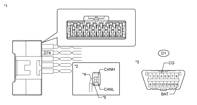
Text in Illustration *1 CAN No. 5 Junction Connector *2 Rear view of wire harness connector (to CAN No. 5 Junction Connector) *3 DLC3 *4 Pink *5 White -
Measure the resistance according to the value(s) in the table below.
Standard Resistance Tester Connection Condition Specified Condition Purpose D74-1 (CANH) - D74-2 (CANL) Ignition switch off 200 Ω or higher Inspection for open or short circuit between bus line D74-1 (CANH) - D1-4 (CG) Ignition switch off 200 Ω or higher Inspection for CANH ground short D74-2 (CANL) - D1-4 (CG) Ignition switch off 200 Ω or higher Inspection for CANL ground short D74-1 (CANH) - D1-16 (BAT) Cable disconnected from negative (-) battery terminal 6 kΩ or higher Inspection for CANH +B short D74-2 (CANL) - D1-16 (BAT) Cable disconnected from negative (-) battery terminal 6 kΩ or higher Inspection for CANL +B short Tech Tips
It is only necessary to perform the inspection in the above table for the result (open or short circuit) that was obtained in the Check CAN MS Bus Wire inspection.
Find the necessary inspection from the Purpose column that matches the result in the Result column from the Check CAN MS Bus Wire inspection.
NG
CHECK FOR SHORT IN CAN MS BUS BRANCH WIRES (OUTER MIRROR CONTROL ECU ASSEMBLY (for Front Passenger Side)) Click here
OK
-
-
CHECK FOR SHORT IN CAN MS BUS WIRES (CAN NO. 5 J/C - MAIN BODY ECU (DRIVER SIDE JUNCTION BLOCK ASSEMBLY))
-
Disconnect the CAN No. 5 junction connector (D73).
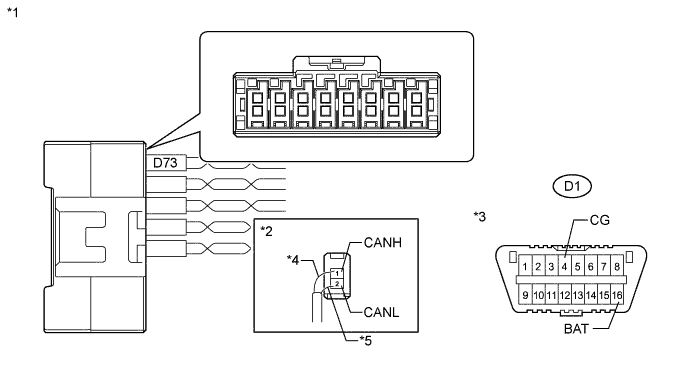
Text in Illustration *1 CAN No. 5 Junction Connector *2 Rear view of wire harness connector (to CAN No. 5 Junction Connector) *3 DLC3 *4 Sky Blue *5 White -
Measure the resistance according to the value(s) in the table below.
Standard Resistance Tester Connection Condition Specified Condition Purpose D73-1 (CANH) - D73-2 (CANL) Ignition switch off 108 to 132 Ω Inspection for open or short circuit between bus line D73-1 (CANH) - D1-4 (CG) Ignition switch off 200 Ω or higher Inspection for CANH ground short D73-2 (CANL) - D1-4 (CG) Ignition switch off 200 Ω or higher Inspection for CANL ground short D73-1 (CANH) - D1-16 (BAT) Cable disconnected from negative (-) battery terminal 6 kΩ or higher Inspection for CANH +B short D73-2 (CANL) - D1-16 (BAT) Cable disconnected from negative (-) battery terminal 6 kΩ or higher Inspection for CANL +B short Tech Tips
It is only necessary to perform the inspection in the above table for the result (open or short circuit) that was obtained in the Check CAN MS Bus Wire inspection.
Find the necessary inspection from the Purpose column that matches the result in the Result column from the Check CAN MS Bus Wire inspection.
NG
CHECK FOR SHORT IN CAN MS BUS WIRES (MAIN BODY ECU (DRIVER SIDE JUNCTION BLOCK ASSEMBLY)) Click here
OK
REPLACE CAN NO. 5 J/C
-
-
CHECK FOR SHORT IN CAN MS BUS BRANCH WIRES (POSITION CONTROL ECU AND SWITCH ASSEMBLY)
-
Reconnect the CAN No. 5 junction connector (D76).
-
Disconnect the position control ECU and switch assembly connectors (T10 and T11).
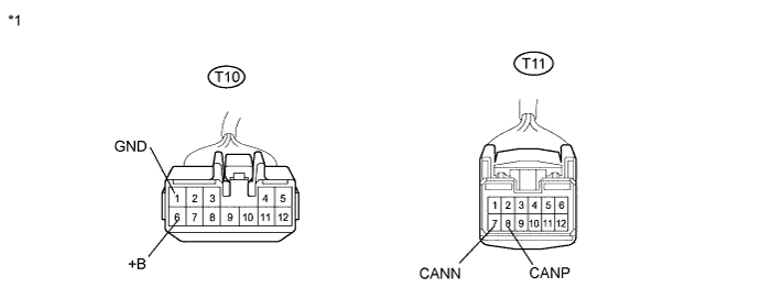
Text in Illustration *1 Front view of wire harness connector
(to Position Control ECU and Switch Assembly)
-
Measure the resistance according to the value(s) in the table below.
Standard Resistance Tester Connection Condition Specified Condition Purpose T11-8 (CANP) - T11-7 (CANN) Ignition switch off 54 to 69 Ω Inspection for open or short circuit between bus line T11-8 (CANP) - T10-1 (GND) Ignition switch off 200 Ω or higher Inspection for CANH ground short T11-7 (CANN) - T10-1 (GND) Ignition switch off 200 Ω or higher Inspection for CANL ground short T11-8 (CANP) - T10-6 (+B) Cable disconnected from negative (-) battery terminal 6 kΩ or higher Inspection for CANH +B short T11-7 (CANN) - T10-6 (+B) Cable disconnected from negative (-) battery terminal 6 kΩ or higher Inspection for CANL +B short Tech Tips
It is only necessary to perform the inspection in the above table for the result (open or short circuit) that was obtained in the Check CAN MS Bus Wire inspection.
Find the necessary inspection from the Purpose column that matches the result in the Result column from the Check CAN MS Bus Wire inspection.
NG
REPAIR OR REPLACE CAN MS BUS BRANCH WIRE OR CONNECTOR (POSITION CONTROL ECU AND SWITCH ASSEMBLY - CAN NO. 5 J/C)
OK
REPLACE POSITION CONTROL ECU AND SWITCH ASSEMBLY Click here
-
-
CHECK FOR SHORT IN CAN MS BUS BRANCH WIRES (OUTER MIRROR CONTROL ECU ASSEMBLY (for Driver Side))
-
Reconnect the CAN No. 5 junction connector (D75).
-
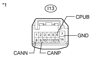
Text in Illustration *1 Front view of wire harness connector
(to Outer Mirror Control ECU Assembly (for Driver Side))
Disconnect the outer mirror control ECU assembly connector (I13).
-
Measure the resistance according to the value(s) in the table below.
Standard Resistance Tester Connection Condition Specified Condition Purpose I13-9 (CANP) - I13-8 (CANN) Ignition switch off 54 to 69 Ω Inspection for open or short circuit between bus line I13-9 (CANP) - I13-7 (GND) Ignition switch off 200 Ω or higher Inspection for CANH ground short I13-8 (CANN) - I13-7 (GND) Ignition switch off 200 Ω or higher Inspection for CANL ground short I13-9 (CANP) - I13-6 (CPUB) Cable disconnected from negative (-) battery terminal 6 kΩ or higher Inspection for CANH +B short I13-8 (CANN) - I13-6 (CPUB) Cable disconnected from negative (-) battery terminal 6 kΩ or higher Inspection for CANL +B short Tech Tips
It is only necessary to perform the inspection in the above table for the result (open or short circuit) that was obtained in the Check CAN MS Bus Wire inspection.
Find the necessary inspection from the Purpose column that matches the result in the Result column from the Check CAN MS Bus Wire inspection.
NG
REPAIR OR REPLACE CAN MS BUS BRANCH WIRE OR CONNECTOR (OUTER MIRROR CONTROL ECU ASSEMBLY (FOR DRIVER SIDE))
OK
REPLACE OUTER MIRROR CONTROL ECU ASSEMBLY (FOR DRIVER SIDE) Click here
-
-
CHECK FOR SHORT IN CAN MS BUS BRANCH WIRES (OUTER MIRROR CONTROL ECU ASSEMBLY (for Front Passenger Side))
-
Reconnect the CAN No. 5 junction connector (D74).
-

Text in Illustration *1 Front view of wire harness connector
(to Outer Mirror Control ECU Assembly (for Front Passenger Side))
Disconnect the outer mirror control ECU assembly connector (H13).
-
Measure the resistance according to the value(s) in the table below.
Standard Resistance Tester Connection Condition Specified Condition Purpose H13-9 (CANP) - H13-8 (CANN) Ignition switch off 54 to 69 Ω Inspection for open or short circuit between bus line H13-9 (CANP) - H13-7 (GND) Ignition switch off 200 Ω or higher Inspection for CANH ground short H13-8 (CANN) - H13-7 (GND) Ignition switch off 200 Ω or higher Inspection for CANL ground short H13-9 (CANP) - H13-6 (CPUB) Cable disconnected from negative (-) battery terminal 6 kΩ or higher Inspection for CANH +B short H13-8 (CANN) - H13-6 (CPUB) Cable disconnected from negative (-) battery terminal 6 kΩ or higher Inspection for CANL +B short Tech Tips
It is only necessary to perform the inspection in the above table for the result (open or short circuit) that was obtained in the Check CAN MS Bus Wire inspection.
Find the necessary inspection from the Purpose column that matches the result in the Result column from the Check CAN MS Bus Wire inspection.
NG
REPAIR OR REPLACE CAN MS BUS BRANCH WIRE OR CONNECTOR (OUTER MIRROR CONTROL ECU ASSEMBLY (FOR FRONT PASSENGER SIDE) - CAN NO. 5 J/C)
OK
REPLACE OUTER MIRROR CONTROL ECU ASSEMBLY (FOR FRONT PASSENGER SIDE) Click here
-
-
CHECK FOR SHORT IN CAN MS BUS WIRES (MAIN BODY ECU (DRIVER SIDE JUNCTION BLOCK ASSEMBLY))
-
Reconnect the CAN No. 5 junction connector (D73).
-
Disconnect the main body ECU (driver side junction block assembly) connector (D48).
Text in Illustration *1 Front view of wire harness connector
(to Main Body ECU (Driver Side Junction Block Assembly))
*2 DLC3 -
Measure the resistance according to the value(s) in the table below.
Standard Resistance Tester Connection Condition Specified Condition Purpose D48-16 (CANP) - D48-15 (CANN) Ignition switch off 108 to 132 Ω Inspection for open or short circuit between bus line D48-16 (CANP) - D1-4 (CG) Ignition switch off 200 Ω or higher Inspection for CANH ground short D48-15 (CANN) - D1-4 (CG) Ignition switch off 200 Ω or higher Inspection for CANL ground short D48-16 (CANP) - D1-16 (BAT) Cable disconnected from negative (-) battery terminal 6 kΩ or higher Inspection for CANH +B short D48-15 (CANN) - D1-16 (BAT) Cable disconnected from negative (-) battery terminal 6 kΩ or higher Inspection for CANL +B short Tech Tips
It is only necessary to perform the inspection in the above table for the result (open or short circuit) that was obtained in the Check CAN MS Bus Wire inspection.
Find the necessary inspection from the Purpose column that matches the result in the Result column from the Check CAN MS Bus Wire inspection.
NG
REPAIR OR REPLACE CAN MS BUS MAIN WIRE OR CONNECTOR (MAIN BODY ECU (DRIVER SIDE JUNCTION BLOCK ASSEMBLY) - CAN NO. 5 J/C)
OK
REPLACE MAIN BODY ECU (DRIVER SIDE JUNCTION BLOCK ASSEMBLY) Click here
-