CAN COMMUNICATION SYSTEM Check CAN Bus Line for Short to GND
DESCRIPTION
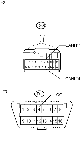
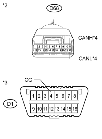
There may be a short circuit between the CAN bus main wire and GND when there is no resistance between terminals 6 (CANH) and 4 (CG) or 14 (CANL) and 4 (CG) of the DLC3.
| Symptom | Trouble Area |
|---|---|
| No resistance exists between terminals 6 (CANH) and 4 (CG) or 14 (CANL) and 4 (CG) of DLC3. |
|
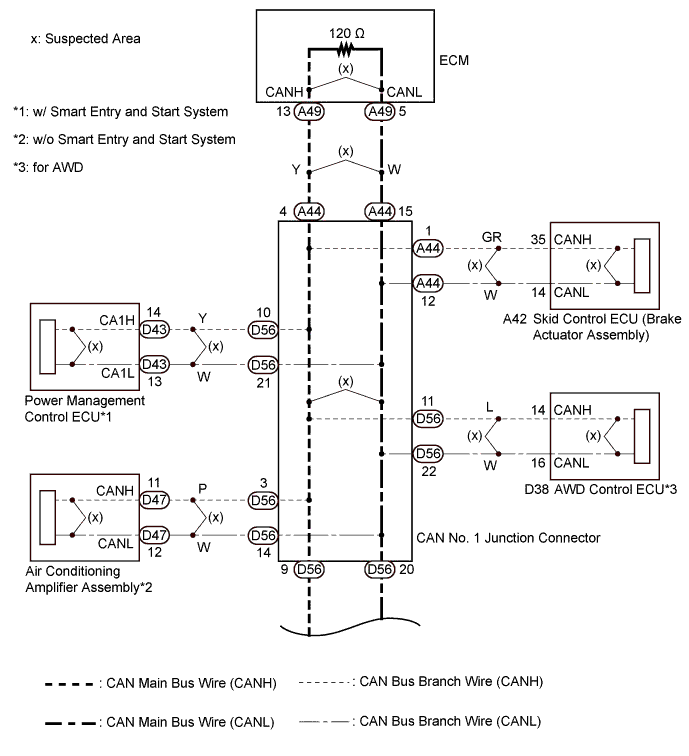
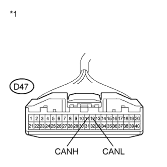
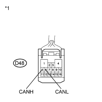
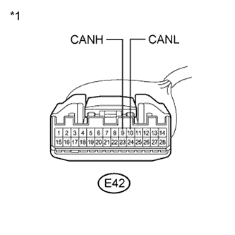
*1: for AWD
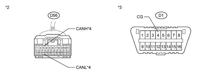
*2: w/ Smart entry and start system
*3: w/o Smart entry and start system
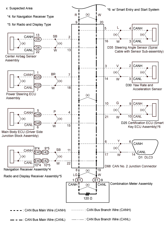
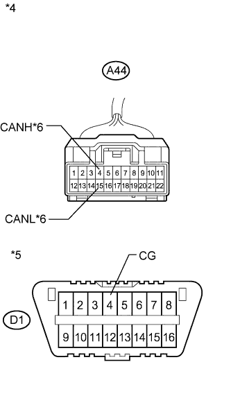
*4: for Navigation receiver type
*5: for Radio and display type
WIRING DIAGRAM
INSPECTION PROCEDURE
Note
-
Turn the ignition switch off before measuring the resistances between CAN bus main wires and between CAN bus branch wires.
-
Turn the ignition switch off before inspecting CAN bus wires for a ground short.
-
After the ignition switch is turned off, check that the key reminder warning system and light reminder warning system are not operating.
-
Before measuring the resistance, leave the vehicle as is for at least 1 minute and do not operate the ignition switch, any other switches or the doors. If any doors need to be opened in order to check connectors, open the doors and leave them open.
Tech Tips
-
Operating the ignition switch, any other switches or a door triggers related ECU and sensor communication on the CAN. This communication will cause the resistance value to change.
-
Even after DTCs are cleared, if a DTC is stored again after driving the vehicle for a while, the malfunction may be occurring due to vibration of the vehicle. In such a case, wiggling the ECUs or wire harness while performing the inspection below may help determine the cause of the malfunction.
PROCEDURE
-
CHECK FOR SHORT TO GND IN CAN BUS WIRE (CAN NO. 1 J/C)
-
Turn the ignition switch off.
-
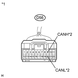
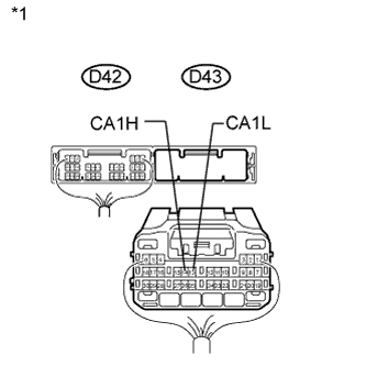
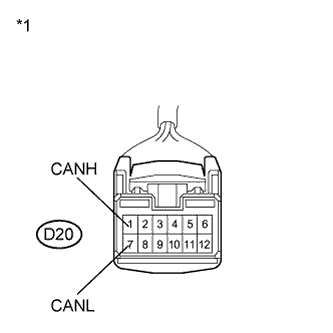
Text in Illustration *1 Front view of wire harness connector
(to CAN No. 1 Junction Connector)
*2 to CAN No. 2 Junction Connector Disconnect the CAN No. 1 junction connector (D56).
-
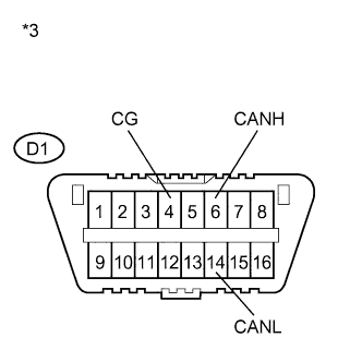
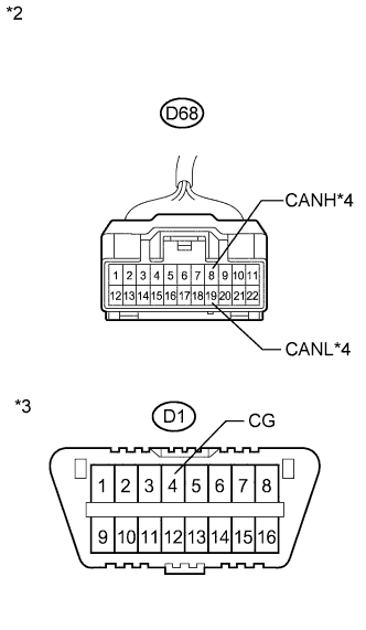
Text in Illustration *3 DLC3 Measure the resistance according to the value(s) in the table below.
Standard Resistance Tester Connection Condition Specified Condition D1-6 (CANH) - D1-4 (CG) Ignition switch off 200 Ω or higher D1-14 (CANL) - D1-4 (CG) Ignition switch off 200 Ω or higher
NG 
CHECK FOR SHORT TO GND IN CAN BUS WIRE (CAN NO. 2 J/C - CAN NO. 1 J/C) Click here
OK 
-
-
CHECK FOR SHORT TO GND IN CAN BUS WIRE (CAN NO. 1 J/C)
-
Disconnect the CAN No. 1 junction connector (A44) .
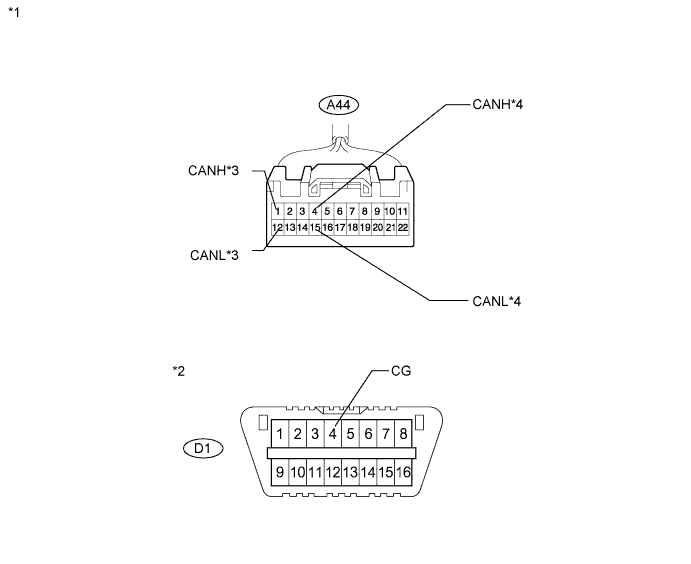
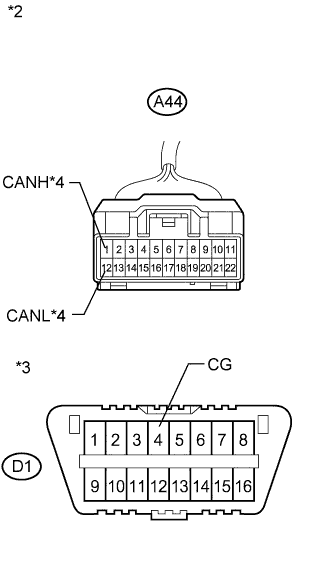
Text in Illustration *1 Front view of wire harness connector (to CAN No. 1 Junction Connector) *2 DLC3 *3 to Skid Control ECU (Brake Actuator Assembly) *4 to ECM -
Measure the resistance according to the value(s) in the table below.
Standard Resistance Tester Connection Condition Specified Condition Connected to A44-1 (CANH) - D1-4 (CG) Ignition switch off 200 Ω or higher Skid control ECU (Brake actuator assembly) A44-12 (CANL) - D1-4 (CG) Ignition switch off 200 Ω or higher A44-4 (CANH) - D1-4 (CG) Ignition switch off 200 Ω or higher ECM A44-15 (CANL) - D1-4 (CG) Ignition switch off 200 Ω or higher Result Result Proceed to OK A NG (Skid control ECU (brake actuator assembly) branch wire) B NG (ECM main wire) C
B
CHECK FOR SHORT TO GND IN CAN BUS WIRE (CAN NO. 1 J/C - SKID CONTROL ECU (BRAKE ACTUATOR ASSEMBLY)) Click here
C
CHECK FOR SHORT TO GND IN CAN BUS WIRE (CAN NO. 1 J/C - ECM) Click here
A
-
-
CHECK FOR SHORT TO GND IN CAN BUS WIRE (CAN NO. 1 J/C)
-
Measure the resistance according to the value(s) in the table below.
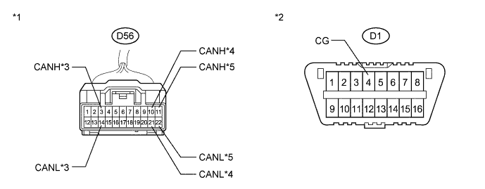
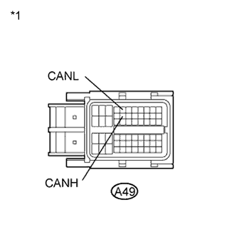
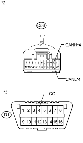
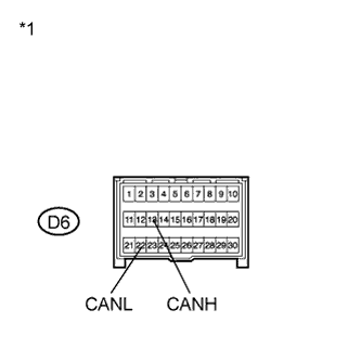
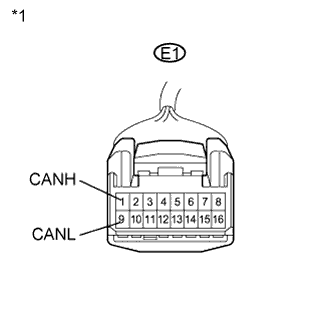
Standard Resistance Tester Connection Condition Specified Condition Connected to D56-3 (CANH) - D1-4 (CG) Ignition switch off 200 Ω or higher Air conditioning amplifier assembly*1 D56-14 (CANL) - D1-4 (CG) Ignition switch off 200 Ω or higher D56-10 (CANH) - D1-4 (CG) Ignition switch off 200 Ω or higher Power management control ECU*2 D56-21 (CANL) - D1-4 (CG) Ignition switch off 200 Ω or higher D56-11 (CANH) - D1-4 (CG) Ignition switch off 200 Ω or higher AWD control ECU*3 D56-22 (CANL) - D1-4 (CG) Ignition switch off 200 Ω or higher
-
*1: w/o Smart entry and start system
-
*2: w/ Smart entry and start system
-
*3: for AWD
Text in Illustration *1 Front view of wire harness connector (to CAN No. 1 Junction Connector) *2 DLC3 *3 to Air Conditioning Amplifier Assembly *4 to Power Management Control ECU *5 to AWD Control ECU Result Result Proceed to OK A NG (Air conditioning amplifier assembly branch wire) B NG (Power management control ECU branch wire) C NG (AWD control ECU branch wire) D -
B
CHECK FOR SHORT TO GND IN CAN BUS WIRE (CAN NO. 1 J/C - AIR CONDITIONING AMPLIFIER ASSEMBLY) Click here
C
CHECK FOR SHORT TO GND IN CAN BUS WIRE (CAN NO. 1 J/C - POWER MANAGEMENT CONTROL ECU) Click here
D
CHECK FOR SHORT TO GND IN CAN BUS WIRE (CAN NO. 1 J/C - AWD CONTROL ECU) Click here
A 
REPLACE CAN NO. 1 J/C
-
-
CHECK FOR SHORT TO GND IN CAN BUS WIRE (CAN NO. 2 J/C - CAN NO. 1 J/C)
-
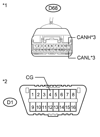
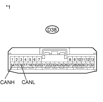
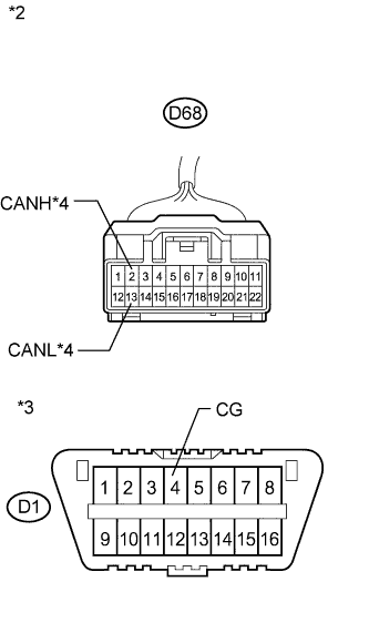
Text in Illustration *1 Front view of wire harness connector
(to CAN No. 2 Junction Connector)
*2 DLC3 *3 to CAN No. 1 Junction Connector Disconnect the CAN No. 2 junction connector.
-
Measure the resistance according to the value(s) in the table below.
Standard Resistance Tester Connection Condition Specified Condition D68-9 (CANH) - D1-4 (CG) Ignition switch off 200 Ω or higher D68-20 (CANL) - D1-4 (CG) Ignition switch off 200 Ω or higher
NG 
REPAIR OR REPLACE CAN BUS MAIN WIRE OR CONNECTOR (CAN NO. 2 J/C - CAN NO. 1 J/C)
OK
-
-
CHECK FOR SHORT TO GND IN CAN BUS WIRE (CAN NO. 2 J/C)
-
Measure the resistance according to the value(s) in the table below.
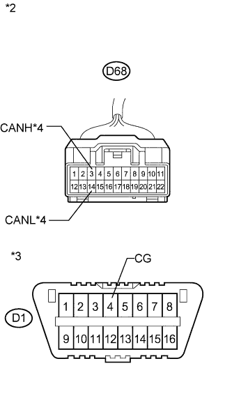
Standard Resistance Tester Connection Condition Specified Condition Connected to D68-2 (CANH) - D1-4 (CG) Ignition switch off 200 Ω or higher Center airbag sensor assembly D68-13 (CANL) - D1-4 (CG) Ignition switch off 200 Ω or higher D68-3 (CANH) - D1-4 (CG) Ignition switch off 200 Ω or higher Yaw rate and acceleration sensor D68-14 (CANL) - D1-4 (CG) Ignition switch off 200 Ω or higher D68-4 (CANH) - D1-4 (CG) Ignition switch off 200 Ω or higher Main body ECU (Driver side junction block assembly) D68-15 (CANL) - D1-4 (CG) Ignition switch off 200 Ω or higher D68-5 (CANH) - D1-4 (CG) Ignition switch off 200 Ω or higher Steering angle sensor (Spiral cable with sensor sub-assembly) D68-16 (CANL) - D1-4 (CG) Ignition switch off 200 Ω or higher Text in Illustration *1 Front view of wire harness connector (to CAN No. 2 Junction Connector) *2 DLC3 *3 to Center Airbag Sensor Assembly *4 to Yaw Rate and Acceleration Sensor *5 to Main Body ECU (Driver Side Junction Block Assembly) *6 to Steering Angle Sensor (Spiral Cable with Sensor Sub-assembly) Result Result Proceed to OK A NG (Center airbag sensor assembly branch wire) B NG (Yaw Rate and Acceleration Sensor branch wire) C NG (Main body ECU (driver side junction block assembly) branch wire) D NG (Steering angle sensor (spiral cable with sensor sub-assembly) branch wire) E
B
CHECK FOR SHORT TO GND IN CAN BUS WIRE (CAN NO. 2 J/C - CENTER AIRBAG SENSOR ASSEMBLY) Click here
C
CHECK FOR SHORT TO GND IN CAN BUS WIRE (CAN NO. 2 J/C - YAW RATE AND ACCELERATION SENSOR) Click here
D
CHECK FOR SHORT TO GND IN CAN BUS WIRE (CAN NO. 2 J/C - MAIN BODY ECU (DRIVER SIDE JUNCTION BLOCK ASSEMBLY)) Click here
E
CHECK FOR SHORT TO GND IN CAN BUS WIRE (CAN NO. 2 J/C - STEERING ANGLE SENSOR (SPIRAL CABLE WITH SENSOR SUB-ASSEMBLY)) Click here
A
-
-
CHECK FOR SHORT TO GND IN CAN BUS WIRE (CAN NO. 2 J/C)
-
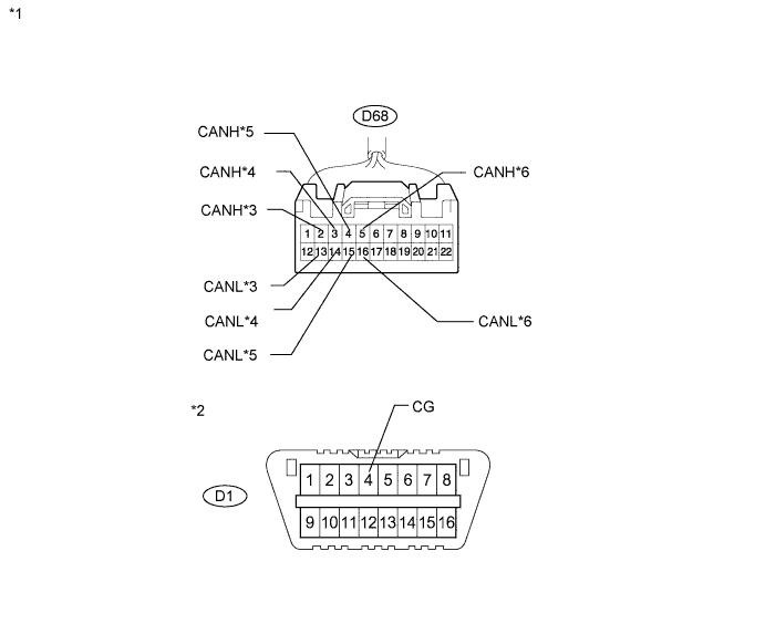
Measure the resistance according to the value(s) in the table below.
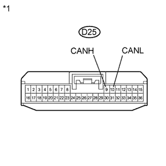
Standard Resistance Tester Connection Condition Specified Condition Connected to D68-6 (CANH) - D1-4 (CG) Ignition switch off 200 Ω or higher DLC3 D68-17 (CANL) - D1-4 (CG) Ignition switch off 200 Ω or higher D68-7 (CANH) - D1-4 (CG) Ignition switch off 200 Ω or higher Power steering ECU assembly D68-18 (CANL) - D1-4 (CG) Ignition switch off 200 Ω or higher D68-8 (CANH) - D1-4 (CG) Ignition switch off 200 Ω or higher Combination meter assembly D68-19 (CANL) - D1-4 (CG) Ignition switch off 200 Ω or higher D68-10 (CANH) - D1-4 (CG) Ignition switch off 200 Ω or higher Certification ECU (Smart key ECU assembly)*1 D68-21 (CANL) - D1-4 (CG) Ignition switch off 200 Ω or higher
-
*1: w/ Smart entry and start system
Text in Illustration *1 Front view of wire harness connector (to CAN No. 2 Junction Connector) *2 DLC3 *3 to DLC3 *4 to Power Steering ECU Assembly *5 to Combination Meter Assembly *6 to Certification ECU (Smart Key ECU Assembly) Result Result Proceed to OK A NG (DLC3 branch wire) B NG (Power steering ECU assembly branch wire) C NG (Combination meter assembly main wire) D NG (Certification ECU (smart key ECU assembly) branch wire) E -
B
REPAIR OR REPLACE CAN BRANCH WIRE CONNECTED TO DLC3
C
CHECK FOR SHORT TO GND IN CAN BUS WIRE (CAN NO. 2 J/C - POWER STEERING ECU ASSEMBLY) Click here
D
CHECK FOR SHORT TO GND IN CAN BUS WIRE (CAN NO. 2 J/C - COMBINATION METER ASSEMBLY) Click here
E
CHECK FOR SHORT TO GND IN CAN BUS WIRE (CAN NO. 2 J/C - CERTIFICATION ECU (SMART KEY ECU ASSEMBLY)) Click here
A
-
-
CHECK FOR SHORT TO GND IN CAN BUS WIRE (CAN NO. 2 J/C)
-
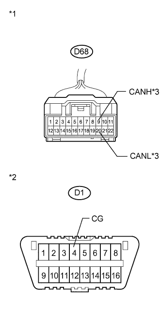
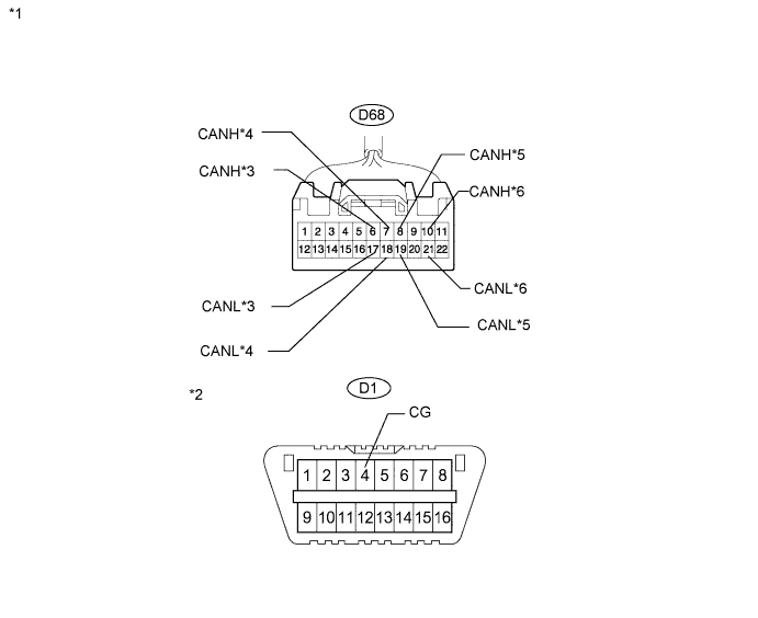
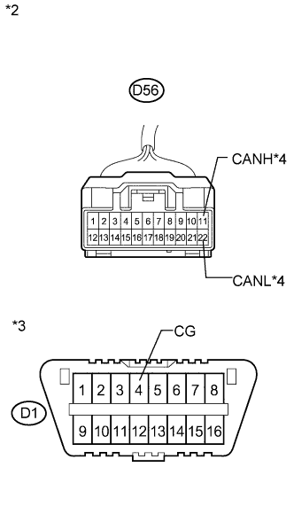
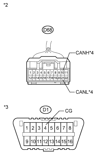
Text in Illustration *1 Front view of wire harness connector (to CAN No. 2 Junction Connector) *2 DLC3 *3
-
to Navigation Receiver Assembly
-
to Radio and Display Receiver Assembly
Measure the resistance according to the value(s) in the table below.
Standard Resistance Tester Connection Condition Specified Condition Connected to D68-11 (CANH) - D1-4 (CG) Ignition switch off 200 Ω or higher
-
Navigation receiver assembly (for Navigation Receiver Type)
-
Radio and display receiver assembly (for Radio and Display Type)
D68-22 (CANL) - D1-4 (CG) Ignition switch off 200 Ω or higher Result Result Proceed to OK A NG (Navigation receiver assembly branch wire) B NG (Radio and display receiver assembly branch wire) C -
B
CHECK FOR SHORT TO GND IN CAN BUS WIRE (CAN NO. 2 J/C - NAVIGATION RECEIVER ASSEMBLY) Click here
C
CHECK FOR SHORT TO GND IN CAN BUS WIRE (CAN NO. 2 J/C - RADIO AND DISPLAY RECEIVER ASSEMBLY) Click here
A
REPLACE CAN NO. 2 J/C
-
-
CHECK FOR SHORT TO GND IN CAN BUS WIRE (CAN NO. 1 J/C - SKID CONTROL ECU (BRAKE ACTUATOR ASSEMBLY))
-
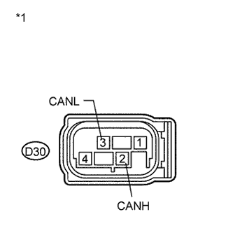
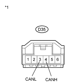
Text in Illustration *1 Front view of wire harness connector:
(to Skid Control ECU (Brake Actuator Assembly))
Disconnect the skid control ECU (brake actuator assembly) connector.
-
Text in Illustration *2 Front view of wire harness connector
(to CAN No. 1 Junction Connector)
*3 DLC3 *4 to Skid Control ECU (Brake Actuator Assembly) Measure the resistance according to the value(s) in the table below.
Standard Resistance Tester Connection Condition Specified Condition A44-1 (CANH) - D1-4 (CG) Ignition switch off 200 Ω or higher A44-12 (CANL) - D1-4 (CG) Ignition switch off 200 Ω or higher
NG
REPAIR OR REPLACE CAN BUS BRANCH WIRE OR CONNECTOR (CAN NO. 1 J/C - SKID CONTROL ECU (BRAKE ACTUATOR ASSEMBLY))
OK
REPLACE BRAKE ACTUATOR ASSEMBLY (SKID CONTROL ECU) Click here
-
-
CHECK FOR SHORT TO GND IN CAN BUS WIRE (CAN NO. 1 J/C - ECM)
-
Text in Illustration *1 Front view of wire harness connector
(to ECM)
Disconnect the ECM connector.
-
Text in Illustration *4 Front view of wire harness connector
(to CAN No. 1 Junction Connector)
*5 DLC3 *6 to ECM Measure the resistance according to the value(s) in the table below.
Standard Resistance Tester Connection Condition Specified Condition A44-4 (CANH) - D1-4 (CG) Ignition switch off 200 Ω or higher A44-15 (CANL) - D1-4 (CG) Ignition switch off 200 Ω or higher
NG
REPAIR OR REPLACE CAN BUS MAIN WIRE OR CONNECTOR (CAN NO. 1 J/C - ECM)
OK
REPLACE ECM Click here
-
-
CHECK FOR SHORT TO GND IN CAN BUS WIRE (CAN NO. 1 J/C - AIR CONDITIONING AMPLIFIER ASSEMBLY)
-
Text in Illustration *1 Front view of wire harness connector
(to Air Conditioning Amplifier Assembly)
Disconnect the air conditioning amplifier assembly connector.
-
Measure the resistance according to the value(s) in the table below.
Standard Resistance Tester Connection Condition Specified Condition D56-3 (CANH) - D1-4 (CG) Ignition switch off 200 Ω or higher D56-14 (CANL) - D1-4 (CG) Ignition switch off 200 Ω or higher Text in Illustration *2 Front view of wire harness connector
(to CAN No. 1 Junction Connector)
*3 DLC3 *4 to Air Conditioning Amplifier Assembly
NG
REPAIR OR REPLACE CAN BUS BRANCH WIRE OR CONNECTOR (CAN NO. 1 J/C - AIR CONDITIONING AMPLIFIER ASSEMBLY)
OK
REPLACE AIR CONDITIONING AMPLIFIER ASSEMBLY Click here
-
-
CHECK FOR SHORT TO GND IN CAN BUS WIRE (CAN NO. 1 J/C - POWER MANAGEMENT CONTROL ECU)
-
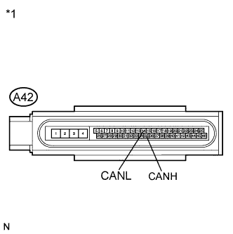
Text in Illustration *1 Rear view of wire harness connector
(to Power Management Control ECU)
Disconnect the power management control ECU connector.
-
Text in Illustration *2 Front view of wire harness connector
(to CAN No. 1 Junction Connector)
*3 DLC3 *4 to Power Management Control ECU Measure the resistance according to the value(s) in the table below.
Standard Resistance Tester Connection Condition Specified Condition D56-10 (CANH) - D1-4 (CG) Ignition switch off 200 Ω or higher D56-21 (CANL) - D1-4 (CG) Ignition switch off 200 Ω or higher
NG
REPAIR OR REPLACE CAN BUS BRANCH WIRE OR CONNECTOR (CAN NO. 1 J/C - POWER MANAGEMENT CONTROL ECU)
OK
REPLACE POWER MANAGEMENT CONTROL ECU Click here
-
-
CHECK FOR SHORT TO GND IN CAN BUS WIRE (CAN NO. 1 J/C - AWD CONTROL ECU)
-
Text in Illustration *1 Front view of wire harness connector
(to AWD Control ECU)
Disconnect the AWD control ECU connector.
-
Text in Illustration *2 Front view of wire harness connector
(to CAN No. 1 Junction Connector)
*3 DLC3 *4 to AWD Control ECU Measure the resistance according to the value(s) in the table below.
Standard Resistance Tester Connection Condition Specified Condition D56-11 (CANH) - D1-4 (CG) Ignition switch off 200 Ω or higher D56-22 (CANL) - D1-4 (CG) Ignition switch off 200 Ω or higher
NG
REPAIR OR REPLACE CAN BUS BRANCH WIRE OR CONNECTOR (CAN NO. 1 J/C - AWD CONTROL ECU)
OK
REPLACE AWD CONTROL ECU Click here
-
-
CHECK FOR SHORT TO GND IN CAN BUS WIRE (CAN NO. 2 J/C - CENTER AIRBAG SENSOR ASSEMBLY)
-
Text in Illustration *1 Front view of wire harness connector
(to Center Airbag Sensor Assembly)
Disconnect the center airbag sensor assembly connector.
-
Text in Illustration *2 Front view of wire harness connector
(to CAN No. 2 Junction Connector)
*3 DLC3 *4 to Center Airbag Sensor Assembly Measure the resistance according to the value(s) in the table below.
Standard Resistance Tester Connection Condition Specified Condition D68-2 (CANH) - D1-4 (CG) Ignition switch off 200 Ω or higher D68-13 (CANL) - D1-4 (CG) Ignition switch off 200 Ω or higher
NG
REPAIR OR REPLACE CAN BUS BRANCH WIRE OR CONNECTOR (CAN NO. 2 J/C - CENTER AIRBAG SENSOR ASSEMBLY)
OK
REPLACE CENTER AIRBAG SENSOR ASSEMBLY Click here
-
-
CHECK FOR SHORT TO GND IN CAN BUS WIRE (CAN NO. 2 J/C - YAW RATE AND ACCELERATION SENSOR)
-
Text in Illustration *1 Front view of wire harness connector
(to Yaw Rate and Acceleration Sensor)
Disconnect the yaw rate and acceleration sensor connector.
-
Text in Illustration *2 Front view of wire harness connector
(to CAN No. 2 Junction Connector)
*3 DLC3 *4 to Yaw Rate and Acceleration Sensor Measure the resistance according to the value(s) in the table below.
Standard Resistance Tester Connection Condition Specified Condition D68-3 (CANH) - D1-4 (CG) Ignition switch off 200 Ω or higher D68-14 (CANL) - D1-4 (CG) Ignition switch off 200 Ω or higher
NG
REPAIR OR REPLACE CAN BUS BRANCH WIRE OR CONNECTOR (CAN NO. 2 J/C - YAW RATE AND ACCELERATION SENSOR)
OK
REPLACE YAW RATE AND ACCELERATION SENSOR Click here
-
-
CHECK FOR SHORT TO GND IN CAN BUS WIRE (CAN NO. 2 J/C - MAIN BODY ECU (DRIVER SIDE JUNCTION BLOCK ASSEMBLY))
-
Text in Illustration *1 Front view of wire harness connector
(to Main Body ECU (Driver Side Junction Block Assembly))
Disconnect the main body ECU (driver side junction block assembly) connector.
-

Text in Illustration *2 Front view of wire harness connector
(to CAN No. 2 Junction Connector)
*3 DLC3 *4 to Main Body ECU (Driver Side Junction Block Assembly) Measure the resistance according to the value(s) in the table below.
Standard Resistance Tester Connection Condition Specified Condition D68-4 (CANH) - D1-4 (CG) Ignition switch off 200 Ω or higher D68-15 (CANL) - D1-4 (CG) Ignition switch off 200 Ω or higher
NG
REPAIR OR REPLACE CAN BUS BRANCH WIRE OR CONNECTOR (CAN NO. 2 J/C - MAIN BODY ECU (DRIVER SIDE JUNCTION BLOCK ASSEMBLY))
OK
REPLACE MAIN BODY ECU (DRIVER SIDE JUNCTION BLOCK ASSEMBLY) Click here
-
-
CHECK FOR SHORT TO GND IN CAN BUS WIRE (CAN NO. 2 J/C - STEERING ANGLE SENSOR (SPIRAL CABLE WITH SENSOR SUB-ASSEMBLY))
-
Text in Illustration *1 Front view of wire harness connector
(to Steering Angle Sensor (Spiral Cable with Sensor Sub-assembly))
Disconnect the steering angle sensor (spiral cable with sensor sub-assembly) connector.
-

Text in Illustration *2 Front view of wire harness connector
(to CAN No. 2 Junction Connector)
*3 DLC3 *4 to Steering Angle Sensor (Spiral Cable with Sensor Sub-assembly) Measure the resistance according to the value(s) in the table below.
Standard Resistance Tester Connection Condition Specified Condition D68-5 (CANH) - D1-4 (CG) Ignition switch off 200 Ω or higher D68-16 (CANL) - D1-4 (CG) Ignition switch off 200 Ω or higher
NG
REPAIR OR REPLACE CAN BUS BRANCH WIRE OR CONNECTOR (CAN NO. 2 J/C - STEERING ANGLE SENSOR (SPIRAL CABLE WITH SENSOR SUB-ASSEMBLY))
OK
REPLACE STEERING ANGLE SENSOR (SPIRAL CABLE WITH SENSOR SUB-ASSEMBLY) Click here
-
-
CHECK FOR SHORT TO GND IN CAN BUS WIRE (CAN NO. 2 J/C - POWER STEERING ECU ASSEMBLY)
-
Text in Illustration *1 Front view of wire harness connector
(to Power Steering ECU Assembly)
Disconnect the power steering ECU assembly connector.
-
Text in Illustration *2 Front view of wire harness connector
(to CAN No. 2 Junction Connector)
*3 DLC3 *4 to Power Steering ECU Assembly Measure the resistance according to the value(s) in the table below.
Standard Resistance Tester Connection Condition Specified Condition D68-7 (CANH) - D1-4 (CG) Ignition switch off 200 Ω or higher D68-18 (CANL) - D1-4 (CG) Ignition switch off 200 Ω or higher
NG
REPAIR OR REPLACE CAN BUS BRANCH WIRE OR CONNECTOR (CAN NO. 2 J/C - POWER STEERING ECU ASSEMBLY)
OK
REPLACE POWER STEERING ECU ASSEMBLY Click here
-
-
CHECK FOR SHORT TO GND IN CAN BUS WIRE (CAN NO. 2 J/C - COMBINATION METER ASSEMBLY)
-
Text in Illustration *1 Front view of wire harness connector
(to Combination Meter Assembly)
Disconnect the combination meter assembly connector.
-
Text in Illustration *2 Front view of wire harness connector
(to CAN No. 2 Junction Connector)
*3 DLC3 *4 to Combination Meter Assembly Measure the resistance according to the value(s) in the table below.
Standard Resistance Tester Connection Condition Specified Condition D68-8 (CANH) - D1-4 (CG) Ignition switch off 200 Ω or higher D68-19 (CANL) - D1-4 (CG) Ignition switch off 200 Ω or higher
NG
REPAIR OR REPLACE CAN BUS MAIN WIRE OR CONNECTOR (CAN NO. 2 J/C - COMBINATION METER ASSEMBLY)
OK
REPLACE COMBINATION METER ASSEMBLY Click here
-
-
CHECK FOR SHORT TO GND IN CAN BUS WIRE (CAN NO. 2 J/C - CERTIFICATION ECU (SMART KEY ECU ASSEMBLY))
-
Text in Illustration *1 Front view of wire harness connector
(to Certification ECU (Smart Key ECU Assembly))
Disconnect the certification ECU (smart key ECU assembly) connector.
-
Text in Illustration *2 Front view of wire harness connector
(to CAN No. 2 Junction Connector)
*3 DLC3 *4 to Certification ECU (Smart Key ECU Assembly) Measure the resistance according to the value(s) in the table below.
Standard Resistance Tester Connection Condition Specified Condition D68-10 (CANH) - D1-4 (CG) Ignition switch off 200 Ω or higher D68-21 (CANL) - D1-4 (CG) Ignition switch off 200 Ω or higher
NG
REPAIR OR REPLACE CAN BUS BRANCH WIRE OR CONNECTOR (CAN NO. 2 J/C - CERTIFICATION ECU (SMART KEY ECU ASSEMBLY))
OK
REPLACE SMART KEY ECU ASSEMBLY (CERTIFICATION ECU)
-
-
CHECK FOR SHORT TO GND IN CAN BUS WIRE (CAN NO. 2 J/C - NAVIGATION RECEIVER ASSEMBLY)
-

Text in Illustration *1 Front view of wire harness connector
(to Navigation Receiver Assembly)
Disconnect the navigation receiver assembly connector.
-
Text in Illustration *2 Front view of wire harness connector
(to CAN No. 2 Junction Connector)
*3 DLC3 *4 to Navigation Receiver Assembly Measure the resistance according to the value(s) in the table below.
Standard Resistance Tester Connection Condition Specified Condition D68-11 (CANH) - D1-4 (CG) Ignition switch off 200 Ω or higher D68-22 (CANL) - D1-4 (CG) Ignition switch off 200 Ω or higher
NG
REPAIR OR REPLACE CAN BUS BRANCH WIRE OR CONNECTOR (CAN NO. 2 J/C - NAVIGATION RECEIVER ASSEMBLY)
OK
REPLACE NAVIGATION RECEIVER ASSEMBLY Click here
-
-
CHECK FOR SHORT TO GND IN CAN BUS WIRE (CAN NO. 2 J/C - RADIO AND DISPLAY RECEIVER ASSEMBLY)
-
Text in Illustration *1 Front view of wire harness connector
(to Radio and Display Receiver Assembly)
Disconnect the radio and display receiver assembly connector.
-
Text in Illustration *2 Front view of wire harness connector
(to CAN No. 2 Junction Connector)
*3 DLC3 *4 to Radio and Display Receiver Assembly Measure the resistance according to the value(s) in the table below.
Standard Resistance Tester Connection Condition Specified Condition D68-11 (CANH) - D1-4 (CG) Ignition switch off 200 Ω or higher D68-22 (CANL) - D1-4 (CG) Ignition switch off 200 Ω or higher
NG
REPAIR OR REPLACE CAN BUS BRANCH WIRE OR CONNECTOR (CAN NO. 2 J/C - RADIO AND DISPLAY RECEIVER ASSEMBLY)
OK
REPLACE RADIO AND DISPLAY RECEIVER ASSEMBLY Click here
-