INTEGRATION RELAY INSPECTION

-
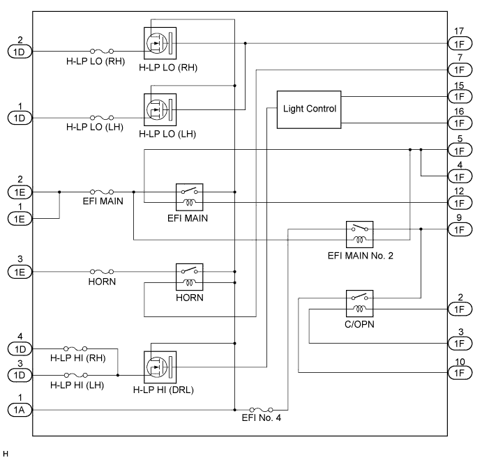
INSPECT INTEGRATION RELAY
-
Inner circuit
-
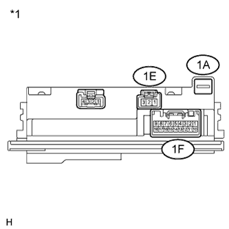
Text in Illustration *1 Component without harness connected
(Integration Relay)
for EFI MAIN No. 2 relay
-
Measure the resistance according to the value(s) in the table below.
Standard Resistance Tester Connection Condition Specified Condition 1A-1 - 1F-9 Battery positive (+) - 1E-1
Battery positive (+) - 1E-2
Battery negative (-) - 1F-4
Battery negative (-) - 1F-5
Below 1 Ω 1A-1 - 1F-9 Always 10 kΩ or higher Tech Tips
If the result is not as specified, replace the integration relay.
-
-
Text in Illustration *1 Component without harness connected
(Integration Relay)
for EFI MAIN relay
-
Measure the resistance according to the value(s) in the table below.
Standard Resistance Tester Connection Condition Specified Condition 1A-1 - 1E-1 Battery positive (+) - 1F-12
Battery negative (-) - 1F-4
Battery negative (-) - 1F-5
Below 1 Ω 1A-1 - 1E-1 Always 10 kΩ or higher 1A-1 - 1E-2 Battery positive (+) - 1F-12
Battery negative (-) - 1F-4
Battery negative (-) - 1F-5
Below 1 Ω 1A-1 - 1E-2 Always 10 kΩ or higher Tech Tips
If the result is not as specified, replace the integration relay.
-
-
Text in Illustration *1 Component without harness connected
(Integration Relay)
for C/OPN relay
-
Measure the resistance according to the value(s) in the table below.
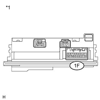
Standard Resistance Tester Connection Condition Specified Condition 1F-9 - 1F-10 Battery positive (+) - 1F-2
Battery negative (-) - 1F-3
Below 1 Ω 1F-9 - 1F-10 Always 10 kΩ or higher Tech Tips
If the result is not as specified, replace the integration relay.
-
-
Text in Illustration *1 Component without harness connected
(Integration Relay)
for HORN relay
-
Measure the voltage according to the value(s) in the table below.
Standard Voltage Tester Connection Condition Specified Condition 1E-3 - Battery negative (-) Battery positive (+) - 1A-1
Battery negative (-) - 1F-7
11 to 14 V Tech Tips
If the result is not as specified, replace the integration relay.
-
-
for H-LP LO (LH) relay
-
Text in Illustration *1 Component without harness connected
(Integration Relay)
Measure the voltage according to the value(s) in the table below.
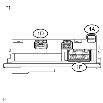
Standard Voltage Tester Connection Condition Specified Condition 1D-1 - Battery negative (-) Battery positive (+) - 1A-1
Battery negative (-) - 1F-17
11 to 14 V Tech Tips
If the result is not as specified, replace the integration relay.
-
-
for H-LP LO (RH) relay
-
Text in Illustration *1 Component without harness connected
(Integration Relay)
Measure the voltage according to the value(s) in the table below.
Standard Voltage Tester Connection Condition Specified Condition 1D-2 - Battery negative (-) Battery positive (+) - 1A-1
Battery negative (-) - 1F-17
11 to 14 V Tech Tips
If the result is not as specified, replace the integration relay.
-
-
for H-LP HI (DRL) relay
-
Text in Illustration *1 Component without harness connected
(Integration Relay)
Check for pulses according to the value(s) in the table below.
Standard Tester Connection Condition Specified Condition 1D-3 - Battery negative (-) Battery positive (+) - 1A-1
Battery negative (-) - 1F-15
Battery negative (-) - 1F-16
Pulse generation 1D-4 - Battery negative (-) Battery positive (+) - 1A-1
Battery negative (-) - 1F-15
Battery negative (-) - 1F-16
Pulse generation Tech Tips
If the result is not as specified, replace the integration relay.
-
-
-