NAVIGATION SYSTEM (for Navigation Receiver Type) OPERATION CHECK

-
CHECK NAVIGATION SYSTEM NORMAL CONDITION
-
If the symptom is applicable to any of the following, it is intended behavior, and not a malfunction.
Symptom Answer A longer route than expected is chosen. Depending on the road conditions, the navigation receiver assembly may determine that a longer route is quicker. Even when distance priority is high, the shortest route is not shown. Some routes may not be advised due to safety concerns. When the vehicle is put into motion immediately after the engine starts, the navigation system deviates from the correct position. If the vehicle starts before the navigation system activates, the system may not react. When driving on certain types of roads, especially new roads, the vehicle position deviates from the correct position. When the vehicle is driving on new roads not available on the map data, the system attempts to match it to another nearby road, causing the position mark to deviate. -
The following symptoms are not malfunctions, but are caused by errors inherent in the GPS, gyro sensor, vehicle speed signal or navigation receiver assembly.
-
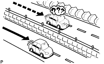
The current position mark may be displayed on a nearby parallel road.
-
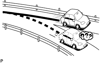
Immediately after a fork in the road, the current vehicle position mark may be displayed on the wrong road.
-
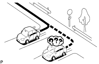
When the vehicle turns right or left at an intersection, the current vehicle position mark may be displayed on a nearby parallel road.
-
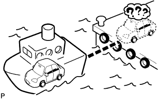
When the vehicle is carried, such as on a ferry, and the vehicle itself is not driving, the current vehicle position mark may be displayed in the position where the vehicle was until a measurement can be performed by the GPS.
-
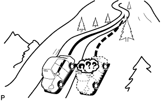
When the vehicle travels on a steep hill, the current vehicle position mark may deviate from the correct position.
-
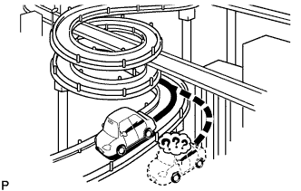
When the vehicle makes a continuous turn (e.g. 360, 720, 1080 degrees), the current vehicle position mark may deviate from the correct position.
-
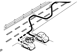
When the vehicle moves erratically, such as constant lane changes, the current vehicle position mark may deviate from the correct position.
-
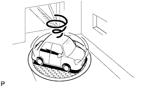
When the ignition switch is turned to ACC or ON and the vehicle is turned on a turntable before parking, the current vehicle position mark may not indicate the correct direction. The same will occur when the vehicle comes out of the parking garage.
-
When the vehicle travels on a snowy road or a mountain path with tire chains installed or using a spare tire, the current vehicle position mark may deviate from the correct position.
-
When the tires are changed, the current vehicle position mark may deviate from the correct position.
Tech Tips
-
A change in tire diameter may cause a speed sensor error.
-
Performing "tire change" in calibration mode will allow the system to correct the current vehicle position faster.
-
-
-
-
CHECK PANEL & STEERING SWITCH
Tech Tips
-
The navigation receiver assembly panel switches and steering switches are checked in the following procedure.
-
Illustrations may differ from the actual vehicle screen depending on the device settings and options. Therefore, some detailed areas may not be shown exactly the same as on the actual vehicle screen.
-
Enter diagnostic mode Click here.
-
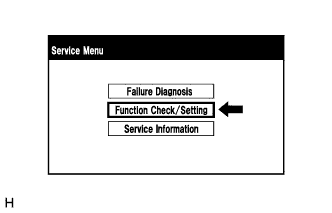
Select "Function Check/Setting" from the "Service Menu" screen.
-
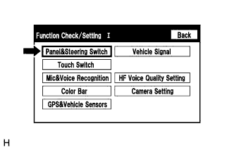
Select "Panel & Steering Switch" from the "Function Check/Setting I" screen.
-
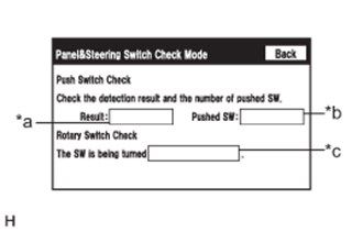
Panel & Steering Switch Check Mode
Screen Description Display Content *a: Switch condition "Pushed" is displayed when any switch is pushed *b: Number of switches pushed
-
Number of switches pushed at once is displayed
-
If 3 switches are pushed at once, "3" or "More than 3" is displayed
-
If 4 or more switches are pushed at once, "More than 3" is displayed
*c: Rotary switch direction Direction of rotary switch is displayed
-
Operate each switch and check that the switch conditions are correctly displayed.
Note
When the "SETUP" switch is pressed and held for 3 seconds or more, diagnostic mode will be canceled.
-
-
-
CHECK TOUCH SWITCH
Tech Tips
-
The touch switches on the screen are checked in the following procedure.
-
Illustrations may differ from the actual vehicle screen depending on the device settings and options. Therefore, some detailed areas may not be shown exactly the same as on the actual vehicle screen.
-
Enter diagnostic mode Click here.
-
Select "Function Check/Setting" from the "Service Menu" screen.
-
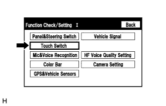
Select "Touch Switch" from the "Function Check/Setting I" screen.
-
Touch Switch Check
-
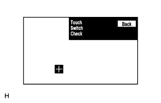
Touch the display anywhere in the open area to perform the check when the "Touch Switch Check" screen is displayed.
Tech Tips
-
A "+" mark is displayed where the display is touched.
-
The "+" mark remains on the display even after your finger is removed.
-
-
-
-
CHECK MIC & VOICE RECOGNITION
Tech Tips
-
The microphone and microphone input level are checked in the following procedure.
-
Illustrations may differ from the actual vehicle screen depending on the device settings and options. Therefore, some detailed areas may not be shown exactly the same as on the actual vehicle screen.
-
Enter diagnostic mode Click here.
-
Select "Function Check/Setting" from the "Service Menu" screen.
-
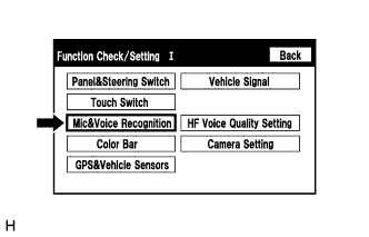
Select "Mic & Voice Recognition" from the "Function Check/Setting I" screen.
-
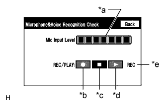
Microphone & Voice Recognition Check
Screen Description Display Content *a: Microphone input level meter Monitors the microphone input level every 0.1 seconds and displays the results in 8 different levels. *b: Recording switch Starts recording. *c: Stop switch Stops recording and playing. *d: Play switch Plays the recorded voice. *e: Recording indicator Comes on while recording.
-
When speaking into the microphone, check that the microphone input level meter changes according to the input level.
Tech Tips
The microphone is active at all times when this screen is displayed.
-
Push the recording switch and perform voice recording.
Tech Tips
-
Select the recording switch with the blower motor of the air conditioning system stopped. If an outlet of the air conditioning system is facing the microphone, noise may be recorded.
-
While recording or playing, the switches other than the stop switch cannot be pushed.
-
When no recording is present, the play switch cannot be pushed.
-
Recording will stop after 5 seconds or when the stop switch is pushed.
-
-
Check that the recording indicator remains on while recording and that the recording can be played normally.
-
-
-
CHECK COLOR BAR
Tech Tips
-
The display color on the screen is checked in the following procedure.
-
Illustrations may differ from the actual vehicle screen depending on the device settings and options. Therefore, some detailed areas may not be shown exactly the same as on the actual vehicle screen.
-
Enter diagnostic mode Click here.
-
Select "Function Check/Setting" from the "Service Menu" screen.
-
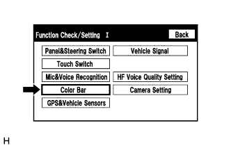
Select "Color Bar" from the "Function Check/Setting I" screen.
-
Color Bar Check Mode
-
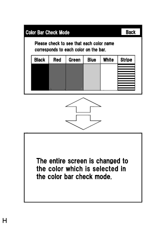
Select a color bar from the "Color Bar Check Mode" screen.
-
Check the display color.
Tech Tips
-
The entire screen turns to the color or stripe selected.
-
Touching the display will return to the "Color Bar Check Mode" screen.
-
-
-
-
CHECK GPS & VEHICLE SENSORS
Tech Tips
-
GPS information, vehicle signals and sensor signals are checked in the following procedure.
-
Illustrations may differ from the actual vehicle screen depending on the device settings and options. Therefore, some detailed areas may not be shown exactly the same as on the actual vehicle screen.
-
Enter diagnostic mode Click here.
-
Select "Function Check/Setting" from the "Service Menu" screen.
-
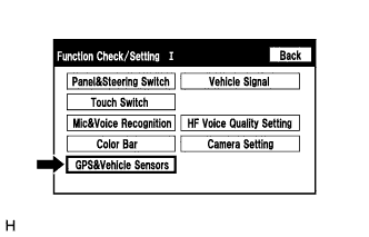
Select "GPS & Vehicle Sensors" from the "Function Check/Setting I" screen.
-
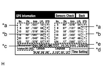
GPS Information
*a: Satellite Information Description Display Content No. Number of the target GPS satellite. Elv Elevation angle of the target GPS satellite. Azm Direction of the target GPS satellite LVL The GPS signal level *b: Receiving Condition Description Display Content P The system is using the GPS signal for location. T The system is tracking the GPS signal for location. U The system is receiving a GPS signal, but is not using it for location. - The system cannot receive a GPS signal. (Searching a GPS Signal) *c: Measurement Status Description Display Content OK (H3D) High accuracy 3-dimensional location method is being used. OK (H2D) High accuracy 2-dimensional location method is being used. OK (3D) 3-dimensional location method is being used. OK (2D) 2-dimensional location method is being used. NG Location data cannot be used. error Reception error has occurred. - Any other state. *d: Position Information Description Display Content Position Latitude and longitude information on the current position is displayed. *e: Date Information Description Display Content Date The date/time information obtained from GPS signals is displayed in Greenwich Mean Time (GMT). Tech Tips
-
This screen is updated once per second.
-
Information from a maximum of 12 satellites is displayed on the screen.
-
When the "GPS Information" screen is displayed, check the GPS conditions.
-
-
Select "Sensors Check" from the "GPS Information" screen.
-
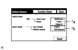
Vehicle Sensors
Screen Description Display Content *a: Vehicle signal Vehicle speed signal condition is displayed. *b: Sensor signal Gyro sensor output condition is displayed. Tech Tips
This screen is updated once per second.
-
Check all the signals and sensors when vehicle signal information is displayed.
-
-
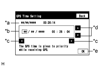
GPS Time Setting
Screen Description Display Content *a: Time display Displays the date and time in the device. *b: Time setting screen Setting is possible only when GPS signals are not being received. *c: Cursor movement switch Moves the cursor on the date and time setting screen to the right and left. *d: Adjustment switch Adjusts values of items selected by the cursor. *e: OK switch Selecting this switch after setting the date and time updates the date and time in the device (only when GPS signals are not received).
-
When GPS signals are not being received, the date and time in the device can be adjusted.
Tech Tips
-
The G-BOOK system cannot be used in areas where GPS signals are not being received. As a result, when using the G-BOOK system in areas such as indoors, set the GPS time from the GPS time setting screen.
-
Time setting is possible only when GPS signals are not being received. When the navigation system is receiving GPS signals, priority is given to displaying the time and date received via GPS.
-
-
-
-
CHECK VEHICLE SIGNAL
Tech Tips
-
Vehicle signals received by the navigation receiver assembly are checked in the following procedure.
-
Illustrations may differ from the actual vehicle screen depending on the device settings and options. Therefore, some detailed areas may not be shown exactly the same as on the actual vehicle screen.
-
Enter diagnostic mode Click here.
-
Select "Function Check/Setting" from the "Service Menu" screen.
-
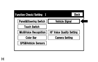
Select "Vehicle Signal" from the "Function Check/Setting I" screen.
-
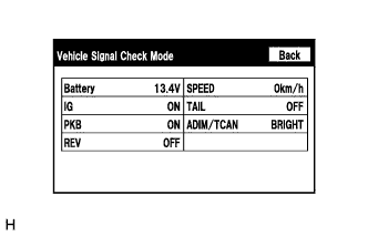
Vehicle Signal Check Mode
Screen Description Display Content Battery Battery voltage is displayed. IG Ignition switch ON/OFF state is displayed. PKB Parking brake ON/OFF state is displayed. REV Reverse signal ON/OFF state is displayed. SPEED Vehicle speed is displayed in km/h. TAIL Tail signal (light control switch) ON/OFF state is displayed. ADIM/TCAN Brightness state DIM (with)/BRIGHT (without) is displayed. Tech Tips
-
Only items sending vehicle signals will be displayed.
-
This screen displays vehicle signals input to the navigation receiver assembly.
-
This screen is updated once per second.
-
When the "Vehicle Signal Check Mode" screen is displayed, check all the vehicle signal conditions.
-
-
-
CHECK HANDS-FREE VOICE QUALITY AND VOLUME SETTING
Note
-
Adjustment of the settings is required for each registered cellular phone.
-
If no cellular phone has been registered, all switches cannot be selected.
Tech Tips
-
The hands-free volume of a "Bluetooth" compatible phone can be adjusted using the following procedure.
-
Illustrations may differ from the actual vehicle screen depending on the device settings and options. Therefore, some detailed areas may not be shown exactly the same as on the actual vehicle screen.
-
Enter diagnostic mode Click here.
-
Select "Function Check/Setting" from the "Service Menu" screen.
-
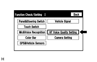
Select "HF Voice Quality Setting" from the "Function Check/Setting I" screen.
-
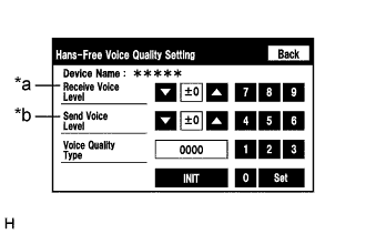
Hands-Free Voice Quality Setting (Receive/Send Voice Level adjustment)
Screen Description Display Content *a: Receive voice level adjustment Setting for the voice level received from "Bluetooth" compatible phones. *b: Send voice level adjustment Setting for the voice level sent from "Bluetooth" compatible phones. Note
Sound quality may deteriorate when the receive voice or send voice level is changed more than necessary. For this reason, check that the received voice or sent voice quality is still acceptable after changing this setting.
-
If the voice level is low, press the up button, and if the voice level is loud, press the down button.
Tech Tips
-
Settings will be applied when the up or down button is selected.
-
The received voice level adjustment ranges from -5 to +1.
-
The sent voice level adjustment ranges from -5 to +4.
-
The initial level is "0".
-
-
-
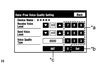
Screen Description *a Numeric keypad *b Setting button *c Reset button Hands-Free Voice Quality Setting (Voice Quality Type adjustment)
-
If necessary, refer to the table below to adjust the voice quality type with the numeric keypad.
-
When adjusting the settings, use the number pad on the screen to input the voice quality type according to the table.
Settings Parameter Target Phenomenon Voice Quality Type Positive Effect of Changing Voice Quality Negative Effect of Changing Voice Quality A
(Noise)
The change in background noise the other party hears becomes unpleasant. 1000 The change in background noise the other party hears is reduced. Background noise when not talking becomes large. B
(Noise)
The volume of the noise the other party hears temporarily becomes large. 2000 The temporary noise is reduced. The volume of voice may drop temporarily. C
(Echo)
The other party hears weak echoes. 0100 The amount of echo is reduced (low level). Sound quality of the other party deteriorates (low level). D
(Echo)
The other party hears strong echoes. 0200 The amount of echo is reduced (high level). Sound quality of the other party deteriorates (high level). E
(Quality)
The other party hears harsh noises. 0010 Sound the other party hears becomes soft. Sound the other party hears becomes muffled. F
(Quality)
You hear harsh noises. 0020 Sound you hear becomes soft. Sound you hear becomes muffled. Settings (When Multiple Phenomenon Occurred) Parameter Target Phenomenon Voice Quality Type Positive Effect of Changing Voice Quality Negative Effect of Changing Voice Quality A+C The change in background noise the other party hears becomes unpleasant and the other party hears weak echoes. 1100
-
The change in background noise the other party hears is reduced.
-
The amount of echo is reduced (low level).
-
Background noise when not talking becomes large.
-
Sound quality of the other party deteriorates (low level).
A+D The change in background noise the other party hears becomes unpleasant and the other party hears strong echoes. 1200
-
The change in background noise the other party hears is reduced.
-
The amount of echo is reduced (high level).
-
Background noise when not talking becomes large.
-
Sound quality of the other party deteriorates (high level).
B+C The volume of the noise the other party hears temporarily becomes large and the other party hears weak echoes. 2100
-
The temporary noise is reduced.
-
The amount of echo is reduced (low level).
-
The volume of voice may drop temporarily.
-
Sound quality of the other party deteriorates (low level).
B+D The volume of the noise the other party hears temporarily becomes large and the other party hears strong echoes. 2200
-
The temporary noise is reduced.
-
The amount of echo is reduced (high level).
-
The volume of voice may drop temporarily.
-
Sound quality of the other party deteriorates (high level).
C+E The other party hears weak echoes and harsh noises. 0110
-
The amount of echo is reduced (low level).
-
Sound the other party hears becomes soft.
-
Sound quality of the other party deteriorates (low level).
-
Sound the other party hears becomes muffled.
C+F The other party hears weak echoes and you hear harsh noises. 0120
-
The amount of echo is reduced (low level).
-
Sound you hear becomes soft.
-
Sound quality of the other party deteriorates (low level).
-
Sound you hear becomes muffled.
Tech Tips
-
The default value is "0000".
-
Settings will be applied when the setting button is selected.
-
If voice quality type values that are not in the table are input, the setting will not be applied and a positive effect may not be gained.
-
If the quality of phone calls decreases due to the changed settings, return the settings to "0000" by pressing the "INIT" switch.
-
-
-
-
CLEAR PASSWORD OF EXPORT/IMPORT MEMORY POINT FUNCTION
Tech Tips
-
This function allows the initialization of a password which was set on the navigation receiver assembly when exporting/importing memory points.
-
Illustrations may differ from the actual vehicle screen depending on the device settings and options. Therefore, some detailed areas may not be shown exactly the same as on the actual vehicle screen.
-
Enter diagnostic mode Click here.
-
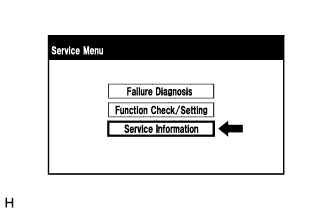
Select "Service Information" from the "Service Menu" screen.
-
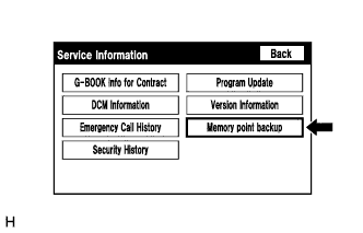
Select "Memory point backup" from the "Service Information" screen.
-
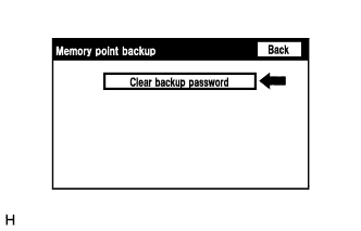
Clear backup password
Tech Tips
Depending on the manufacturer, some component names and versions will be displayed differently.
-
Select "Clear backup password".
-
-