RADIO RECEIVER REMOVAL

-
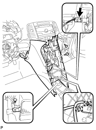
REMOVE UPPER CONSOLE PANEL SUB-ASSEMBLY
-
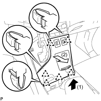
Pull the upper console panel sub-assembly in the direction indicated by the arrow to disengage the 6 clips.
-
Disconnect the connectors and remove the upper console panel sub-assembly.
-
-
REMOVE NO. 2 CONSOLE BOX CARPET
-
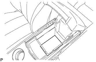
Remove the No. 2 console box carpet.
-
-
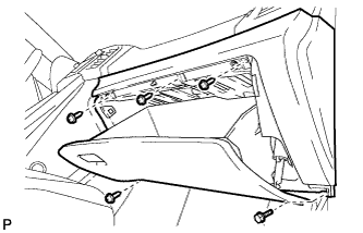
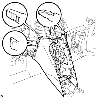
REMOVE CONSOLE BOX ASSEMBLY
-
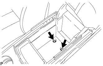
Remove the 2 bolts.
-
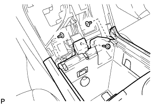
Remove the screw and 2 clips.
-
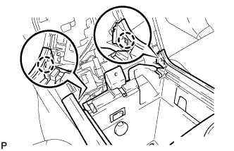
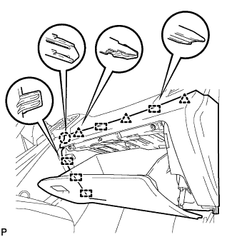
Disengage the 2 claws.
-
Disconnect the connectors and remove the console box assembly.
-
-
REMOVE AIR CONDITIONING CONTROL ASSEMBLY
-
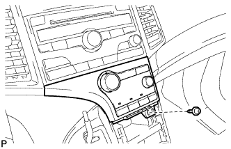
Remove the screw.
-
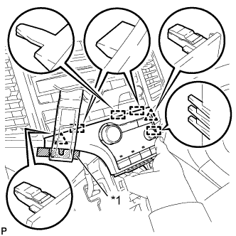
Text in Illustration *1 Protective Tape Apply protective tape to the area shown in the illustration.
-
Using a moulding remover, disengage the 2 clips and 4 guides as shown in the illustration.
-
Disconnect the connector and remove the air conditioning control assembly.
-
-
REMOVE FRONT DOOR SCUFF PLATE RH
Tech Tips
Use the same procedure as for the LH side Click here.
-
REMOVE COWL SIDE TRIM SUB-ASSEMBLY RH
Tech Tips
Use the same procedure as for the LH side Click here.
-
REMOVE NO. 2 INSTRUMENT PANEL UNDER COVER SUB-ASSEMBLY
-
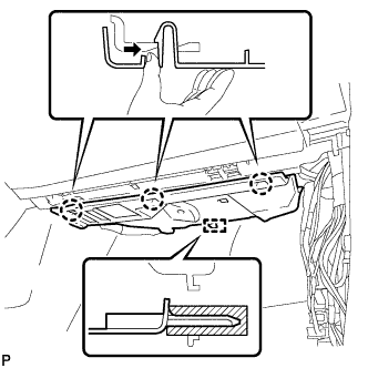
Push the 3 claws in the direction indicated by the arrow to disengage them.
-
Disengage the guide and remove the No. 2 instrument panel under cover sub-assembly.
-
-
REMOVE LOWER INSTRUMENT PANEL SUB-ASSEMBLY
-
Remove the bolt <C> and 4 screws <E> or <F>.
-
Disengage the claw, 3 clips and 5 guides.
-
Disconnect the connectors and remove the lower instrument panel sub-assembly.
-
-
REMOVE SHIFT LEVER KNOB SUB-ASSEMBLY
-
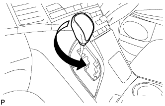
Turn the shift lever knob counterclockwise and remove the shift lever knob sub-assembly.
-
-
REMOVE POSITION INDICATOR HOUSING ASSEMBLY
-
Move the shift lever to N.
-
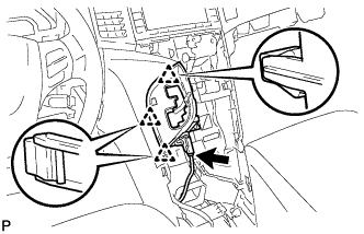
Disconnect the connector.
-
Disengage the 3 clips and remove the position indicator housing assembly.
-
-
REMOVE CONSOLE BOX SUB-ASSEMBLY
-
Remove the 2 screws <E> or <F>.
-
Using a clip remover, remove the clip.
-
Disconnect the connector.
-
Disengage the 2 clamps.
-
Disengage the 2 claws and 4 clips and remove the console box sub-assembly.
-
-
REMOVE NO. 2 INSTRUMENT PANEL SPEAKER PANEL SUB-ASSEMBLY
-
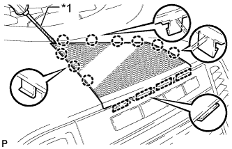
Text in Illustration *1 Protective Tape Using a screwdriver, disengage the 9 claws and 4 guides, and remove the No. 2 instrument panel speaker panel sub-assembly.
Tech Tips
Tape the screwdriver tip before use.
-
-
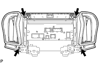
REMOVE RADIO AND DISPLAY RECEIVER ASSEMBLY WITH BRACKET
-
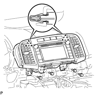
Remove the 4 bolts.
-
Disengage the 2 clips.
-
Disconnect each connector and remove the radio and display receiver assembly with bracket.
-
-
REMOVE INSTRUMENT CLUSTER CENTER FINISH PANEL SUB-ASSEMBLY
-
Remove the 4 screws.
-
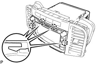
Disengage the 4 claws and remove the instrument cluster center finish panel sub-assembly.
-
-
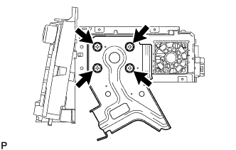
REMOVE NO. 1 RADIO RECEIVER BRACKET
-
w/o Navigation System:
-
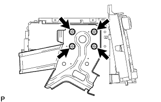
Remove the 4 screws and No. 1 radio receiver bracket.
-
-
w/ Navigation System:
-
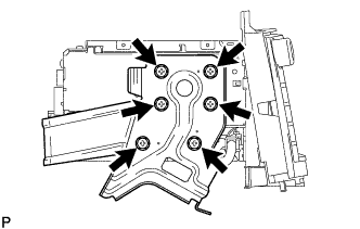
Remove the 6 screws and No. 1 radio receiver bracket.
-
-
-
REMOVE NO. 2 RADIO RECEIVER BRACKET
-
w/o Navigation System:
-
Remove the 4 screws and No. 2 radio receiver bracket.
-
-
w/ Navigation System:
-
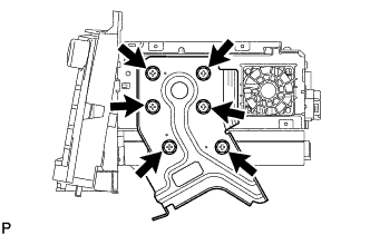
Remove the 6 screws and No. 2 radio receiver bracket.
-
-
-
REMOVE EXTENSION MODULE (w/ Navigation System)
-
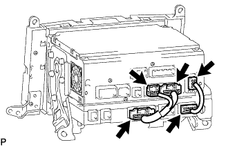
Disconnect each connector to remove the navigation wire and radio cable.
-
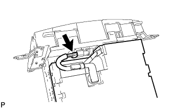
Disconnect the connector to remove the extension module.
-
-
REMOVE RADIO AND DISPLAY RECEIVER ASSEMBLY