STEERING GEAR INSTALLATION

Note
When disconnecting the steering intermediate shaft assembly and pinion shaft of the steering gear assembly, be sure to place matchmarks before servicing.
-
INSTALL TIE ROD ASSEMBLY LH
-
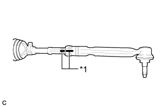
Text in Illustration *1 Matchmark Install the lock nut and tie rod assembly LH to the steering gear assembly until the matchmarks are aligned.
Tech Tips
After adjusting toe-in, tighten the lock nut.
-
-
INSTALL TIE ROD ASSEMBLY RH
Tech Tips
Perform the same procedure as for the LH side.
-
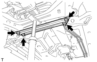
INSTALL STEERING LINK ASSEMBLY (for AWD)
-
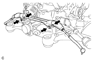
Install the steering link assembly with the 2 bolts and 2 nuts.
- Torque:
- 70 N*m { 713 kgf*cm, 51 ft.*lbf }
Note
-
Make sure to tighten the bolts starting from the left side of the vehicle.
-
Because the nut has its own stopper, do not turn the nut. Tighten the bolt with the nut secured.
-
-
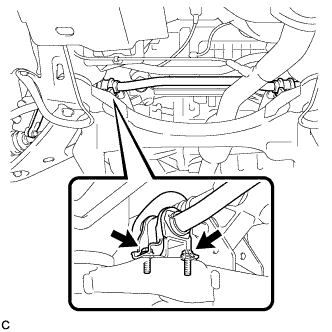
INSTALL FRONT STABILIZER BAR WITH BRACKET (for AWD)
-
Install the front stabilizer bar.
-
-
INSTALL FRONT NO. 1 STABILIZER BRACKET LH (for AWD)
-
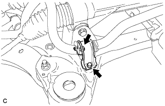
Install the front No. 1 stabilizer bracket LH to the front frame assembly with the 2 bolts.
- Torque:
- 29 N*m { 296 kgf*cm, 21 ft.*lbf }
-
-
INSTALL FRONT NO. 1 STABILIZER BRACKET RH (for AWD)
Tech Tips
Perform the same procedure as for the LH side.
-
INSTALL ENGINE ASSEMBLY WITH TRANSAXLE (for AWD)
Tech Tips
Refer to the procedure from Install Engine Assembly with Transaxle Click here.
-
INSTALL STEERING LINK ASSEMBLY (for 2WD)
-
Install the steering link assembly with the 2 bolts and 2 nuts.
- Torque:
- 70 N*m { 713 kgf*cm, 51 ft.*lbf }
Note
-
Make sure to tighten the bolts starting from the left side of the vehicle.
-
Because the nut has its own stopper, do not turn the nut. Tighten the bolt with the nut secured.
-
-
INSTALL FRONT STABILIZER BAR WITH BRACKET (for 2WD)
-
INSTALL FRONT NO. 1 STABILIZER BRACKET LH (for 2WD)
-
Install the front No. 1 stabilizer bracket LH.
- Torque:
- 29 N*m { 296 kgf*cm, 21 ft.*lbf }
-
-
INSTALL FRONT NO. 1 STABILIZER BRACKET RH (for 2WD)
Tech Tips
Perform the same procedure as for the LH side.
-
INSTALL FRONT FLOOR BRACE (for 2WD)
-
Install the front floor brace with the 4 nuts.
- Torque:
- 11 N*m { 112 kgf*cm, 8 ft.*lbf }
-
-
CONNECT TIE ROD ASSEMBLY LH
-
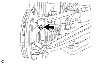
Connect the tie rod assembly LH to the steering knuckle with the nut.
- Torque:
- 49 N*m { 500 kgf*cm, 36 ft.*lbf }
-
Install a new cotter pin.
Note
Further tighten the nut up to 60° if the holes for the cotter pin are not aligned.
-
-
CONNECT TIE ROD ASSEMBLY RH
Tech Tips
Perform the same procedure as for the LH side.
-
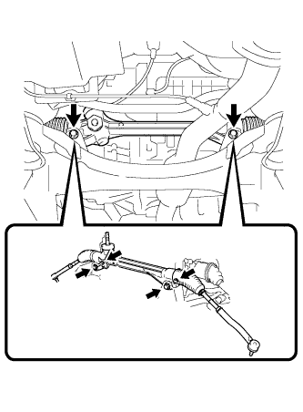
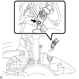
CONNECT STEERING INTERMEDIATE SHAFT ASSEMBLY
-
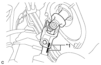
Text in Illustration *1 Matchmark Align the matchmarks on the steering intermediate shaft assembly and steering link assembly.
-
Install the bolt.
- Torque:
- 35 N*m { 357 kgf*cm, 26 ft.*lbf }
-
-
INSTALL FRONT WHEELS (for 2WD)
- Torque:
- 103 N*m { 1050 kgf*cm, 76 ft.*lbf }
-
PLACE FRONT WHEELS FACING STRAIGHT AHEAD (for 2WD)
-
INSTALL NO. 1 ENGINE UNDER COVER (for 2WD)
-
INSTALL NO. 2 ENGINE UNDER COVER (for 2WD)
-
INSPECT AND ADJUST FRONT WHEEL ALIGNMENT (for 2WD)
Tech Tips
Inspect and adjust the front wheel alignment Click here.