STEERING GEAR REMOVAL

Note
When disconnecting the steering intermediate shaft assembly and pinion shaft of the steering gear assembly, be sure to place matchmarks before servicing.
-
PLACE FRONT WHEELS FACING STRAIGHT AHEAD (for 2WD)
-
SECURE STEERING WHEEL
-
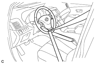
Secure the steering wheel with the seat belt in order to prevent it from rotating.
Tech Tips
This operation is necessary to prevent damage to the spiral cable.
-
-
REMOVE FRONT WHEELS (for 2WD)
-
REMOVE NO. 1 ENGINE UNDER COVER (for 2WD)
-
REMOVE NO. 2 ENGINE UNDER COVER (for 2WD)
-
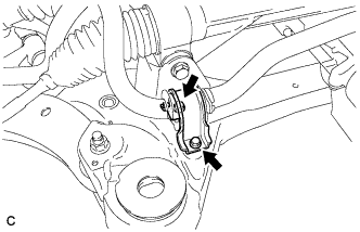
SEPARATE STEERING INTERMEDIATE SHAFT ASSEMBLY
-
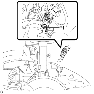
Text in Illustration *1 Matchmark Put matchmarks on the steering intermediate shaft assembly and steering link assembly.
-
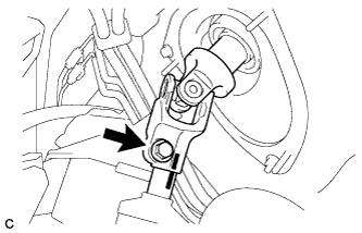
Remove the bolt and slide the steering intermediate shaft assembly.
-
Separate the steering intermediate shaft assembly from the steering link assembly.
-
-
SEPARATE TIE ROD ASSEMBLY LH
-
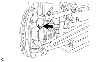
Remove the cotter pin and nut.
-
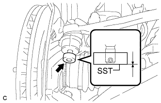
Install SST to the tie rod end.
- SST
- 09960-20010 ( 09961-02060 )
Note
Make sure that the upper ends of the tie rod end and SST are aligned.
-
Using SST, separate the tie rod end from the steering knuckle.
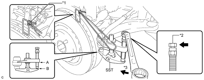
Text in Illustration *1 Tie the string without allowing for any slack. *2 Place the wrench here. *3 Turn - - - SST
- 09960-20010 ( 09961-02010 )
CAUTION:
Apply grease to the threads and end of the SST bolt.
Note
-
When securing SST to the steering knuckle, be sure to tighten the string of SST to prevent it from falling.
-
Install SST so that A and B are parallel.
-
Be sure to place a wrench on the part indicated in the illustration.
-
Do not damage the front disc brake dust cover.
-
Do not damage the ball joint dust cover.
-
Do not damage the steering knuckle.
-
-
SEPARATE TIE ROD ASSEMBLY RH
Tech Tips
Perform the same procedure as for the LH side.
-
REMOVE FRONT FLOOR BRACE (for 2WD)
-
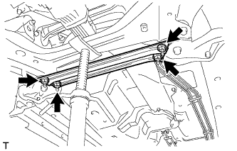
Remove the 4 nuts and front floor brace.
-
-
REMOVE FRONT NO. 1 STABILIZER BRACKET LH (for 2WD)
-
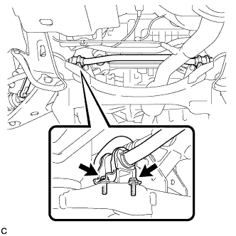
Remove the 2 bolts and front No. 1 stabilizer bracket LH.
-
-
REMOVE FRONT NO. 1 STABILIZER BRACKET RH (for 2WD)
Tech Tips
Perform the same procedure as for the LH side.
-
SEPARATE FRONT STABILIZER BAR WITH BRACKET (for 2WD)
-
Separate the front stabilizer bar with bracket from the front frame assembly.
-
-
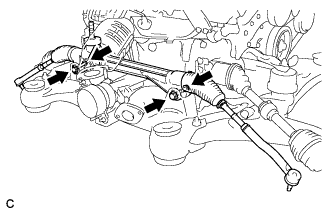
REMOVE STEERING LINK ASSEMBLY (for 2WD)
-
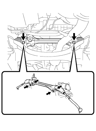
Remove the 2 bolts, 2 nuts and steering link assembly.
Note
Because the nut has its own stopper, do not turn the nut. Loosen the bolt with the nut secured.
-
Pull out the steering link assembly towards the left side of the vehicle while lifting the front stabilizer bar with bracket.
-
-
REMOVE ENGINE ASSEMBLY WITH TRANSAXLE (for AWD)
Tech Tips
Refer to the procedure up to Remove Engine Assembly with Transaxle Click here.
-
REMOVE FRONT NO. 1 STABILIZER BRACKET LH (for AWD)
-
Remove the 2 bolts and front No. 1 stabilizer bracket LH from the front frame assembly.
-
-
REMOVE FRONT NO. 1 STABILIZER BRACKET RH (for AWD)
Tech Tips
Perform the same procedure as for the LH side.
-
REMOVE FRONT STABILIZER BAR WITH BRACKET (for AWD)
-
Remove the front stabilizer bar.
-
-
REMOVE STEERING LINK ASSEMBLY (for AWD)
-
Remove the 2 bolts, 2 nuts and steering link assembly.
Note
Because the nut has its own stopper, do not turn the nut. Loosen the bolt with the nut secured.
-
-
REMOVE TIE ROD ASSEMBLY LH
-
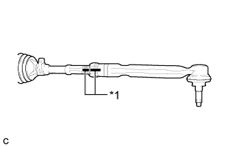
Text in Illustration *1 Matchmark Put matchmarks on the tie rod assembly LH and steering gear assembly.
-
Loosen the lock nut, and remove the tie rod assembly LH and lock nut.
-
-
REMOVE TIE ROD ASSEMBLY RH
Tech Tips
Perform the same procedure as for the LH side.