STEERING COLUMN ASSEMBLY INSTALLATION

-
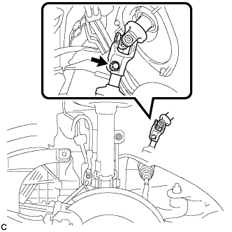
INSTALL STEERING INTERMEDIATE SHAFT ASSEMBLY
-
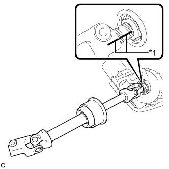
Text in Illustration *1 Matchmark Align the matchmarks on the steering intermediate shaft assembly and the steering column assembly.
-
Install the bolt.
- Torque:
- 35 N*m { 360 kgf*cm, 26 ft.*lbf }
-
-
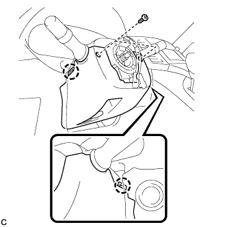
INSTALL STEERING POST ASSEMBLY
-
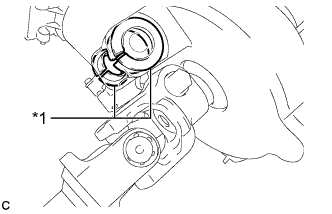
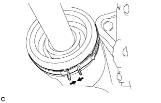
Text in Illustration *1 Bushing Check that the 2 bushings are securely installed to the steering post assembly.
Tech Tips
If the bushings are missing or damaged, replace the steering column assembly with a new one.
-
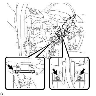
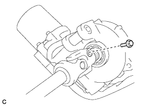
Install the steering post assembly with the bolt and 2 nuts.
- Torque:
- 25 N*m { 255 kgf*cm, 18 ft.*lbf }
Note
-
Do not damage the 2 bushings.
-
Do not line up the bolt hole by prying on the collar or bushings. Only install the bolt in straight, without applying any force to the bushings.
-
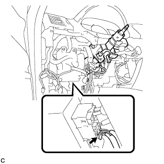
Connect the connectors and engage the wire harness clamps to the steering post assembly.
-
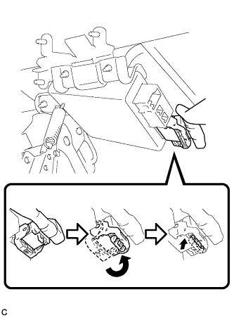
Connect the connector to the power steering ECU assembly.
Tech Tips
Return the lock lever to its original position to connect the connector, and then securely push in the lock of the lock lever as shown in the illustration.
-
Connect the connector to the power steering ECU assembly.
-
-
CONNECT STEERING INTERMEDIATE SHAFT ASSEMBLY
-
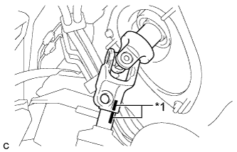
Text in Illustration *1 Matchmark Align the matchmarks on the steering intermediate shaft assembly and the power steering link assembly.
-
Install the bolt.
- Torque:
- 35 N*m { 360 kgf*cm, 26 ft.*lbf }
-
Tighten the clamp.
-
-
INSTALL FRONT WHEEL LH
- Torque:
- 103 N*m { 1050 kgf*cm, 76 ft.*lbf }
-
INSTALL TRANSPONDER KEY AMPLIFIER (w/o Smart Entry and Start System)
-

Connect the connector to the transponder key amplifier.
-
Align the transponder key amplifier with the steering column upper bracket. Tilt the amplifier slightly and slide it into position.
-
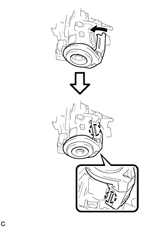
Push the transponder key amplifier, and engage the 2 claws to install the transponder key amplifier to the steering column upper bracket.
-
-
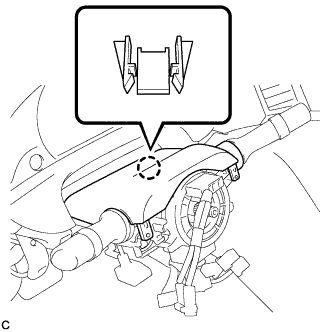
INSTALL TURN SIGNAL SWITCH ASSEMBLY WITH SPIRAL CABLE SUB-ASSEMBLY
-
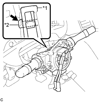
Text in Illustration *1 Clamp *2 Claw Using pliers, expand the clamp.
-
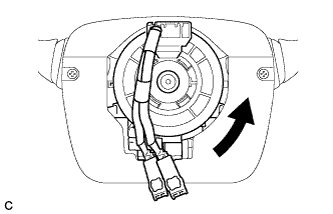
While holding the clamp expanded, install the turn signal switch assembly with spiral cable sub-assembly to the steering column assembly and engage the claw.
-
Return the clamp to its original position.
-
Connect the connectors to the turn signal switch assembly with spiral cable sub-assembly.
-
-
INSTALL UPPER STEERING COLUMN COVER
-
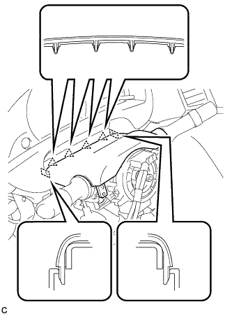
Engage the 4 clips and 2 guides to install the upper steering column cover onto the instrument panel cluster finish panel.
-
Engage the claw to install the upper steering column cover.
-
-
INSTALL LOWER STEERING COLUMN COVER
-
Engage the 2 claws to install the lower steering column cover.
-
Install the 2 screws.
- Torque:
- 2.0 N*m { 20 kgf*cm, 18 in.*lbf }
-
-
INSTALL DRIVER SIDE KNEE AIRBAG ASSEMBLY
-
TURN FRONT WHEELS TO FACE STRAIGHT AHEAD
-
ADJUST SPIRAL CABLE WITH SENSOR SUB-ASSEMBLY
-
Check that the ignition switch is off.
-
Check that the cable is disconnected from the negative (-) battery terminal.
CAUTION:
Wait at least 90 seconds after disconnecting the cable from the negative (-) battery terminal to disable the SRS system.
-
Rotate the spiral cable counterclockwise slowly by hand until it stops.
Note
Do not turn the spiral cable using the airbag wire harness.
-
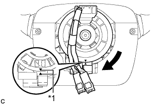
Text in Illustration *1 Alignment Mark Rotate the spiral cable clockwise approximately 2.5 turns to align the alignment marks.
Note
Do not turn the spiral cable using the airbag wire harness.
Tech Tips
The spiral cable will rotate approximately 2.5 turns to both the left and right from the center.
-
-
INSTALL STEERING WHEEL ASSEMBLY
-
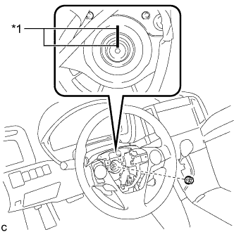
Text in Illustration *1 Matchmark Install the steering wheel assembly aligning the matchmarks on the steering wheel assembly and steering main shaft.
-
Install the steering wheel assembly set nut.
- Torque:
- 50 N*m { 510 kgf*cm, 37 ft.*lbf }
-
Connect each connector to the spiral cable sub-assembly.
-
-
INSPECT STEERING WHEEL CENTER POINT
-
INSTALL STEERING PAD
-
INITIALIZE ROTATION ANGLE SENSOR AND CALIBRATE TORQUE SENSOR ZERO POINT