STEERING COLUMN ASSEMBLY REMOVAL

CAUTION:
Some of these service operations affect the SRS airbag system. Read the precautionary notices concerning the SRS airbag system before servicing the steering column Click here.
-
PRECAUTION
Tech Tips
-
TURN FRONT WHEELS TO FACE STRAIGHT AHEAD
-
REMOVE FRONT WHEEL LH
-
REMOVE STEERING PAD
-
REMOVE STEERING WHEEL ASSEMBLY
-
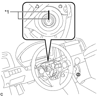
Text in Illustration *1 Matchmark Remove the steering wheel assembly set nut.
-
Put matchmarks on the steering wheel assembly and the steering main shaft.
-
Disconnect each connector from the spiral cable sub-assembly.
-
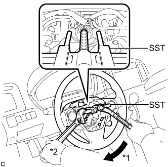
Text in Illustration *1 Turn *2 Hold Using SST, remove the steering wheel assembly.
- SST
- 09950-50013 ( 09951-05010, 09952-05010, 09953-05020, 09954-05070 )
Note
-
Apply a small amount of grease to the threads and tip of SST (09953-05020) before use.
-
Do not rotate the spiral cable with the battery connected and the ignition switch ON.
-
Ensure that the steering wheel is installed and aligned straight when inspecting the steering sensor.
-
-
REMOVE DRIVER SIDE KNEE AIRBAG ASSEMBLY
-
REMOVE LOWER STEERING COLUMN COVER
-
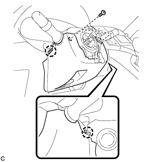
Remove the 2 screws.
-
Push the right and left sides of the lower steering column cover, and disengage the 2 claws to remove the lower steering column cover.
-
-
REMOVE UPPER STEERING COLUMN COVER
-
Disengage the claw.
-
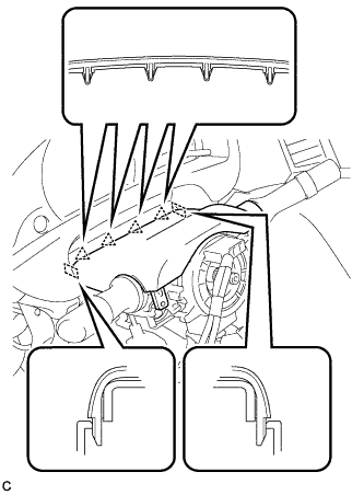
Disengage the 4 clips and 2 guides to remove the upper steering column cover.
-
-
REMOVE TURN SIGNAL SWITCH ASSEMBLY WITH SPIRAL CABLE SUB-ASSEMBLY
-
Disconnect the connectors from the turn signal switch assembly with spiral cable sub-assembly.
-
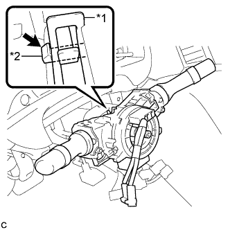
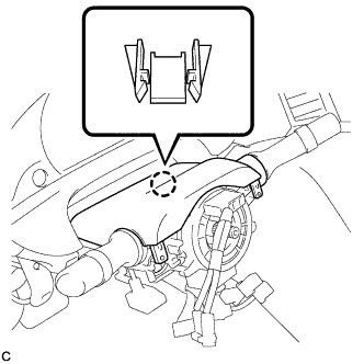
Text in Illustration *1 Clamp *2 Claw Using pliers, expand the clamp.
-
While holding the clamp expanded, raise the claw using a screwdriver to disengage it, and then remove the turn signal switch assembly with spiral cable sub-assembly from the steering column assembly.
Note
-
Do not replace the spiral cable with the battery connected and the ignition switch on.
-
Do not rotate the spiral cable without the steering wheel with the battery connected and the ignition switch on.
-
Ensure that the steering wheel is installed and aligned straight when inspecting the steering sensor.
-
Do not remove the steering sensor from the spiral cable.
-
-
-
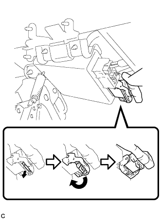
REMOVE TRANSPONDER KEY AMPLIFIER (w/o Smart Entry and Start System)
-
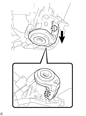
Slide the transponder key amplifier to disengage the 2 claws as shown in the illustration.
-

Disconnect the connector and remove the transponder key amplifier.
-
-
SEPARATE STEERING INTERMEDIATE SHAFT ASSEMBLY
-
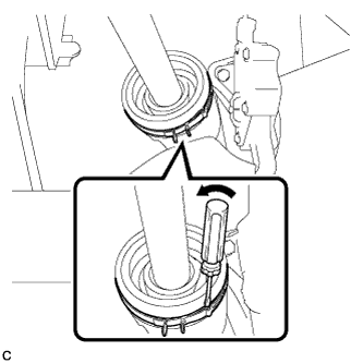
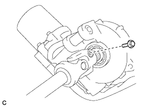
Using a screwdriver, loosen the clamp.
-
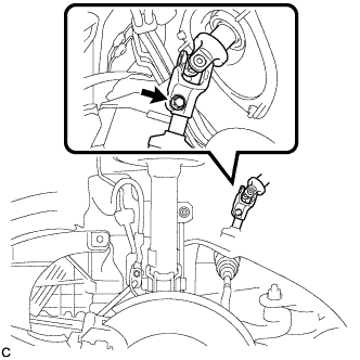
Remove the bolt.
Note
Do not separate the steering intermediate shaft assembly from the power steering link assembly.
-
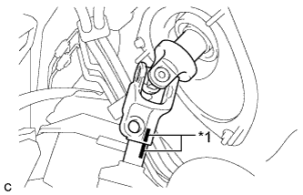
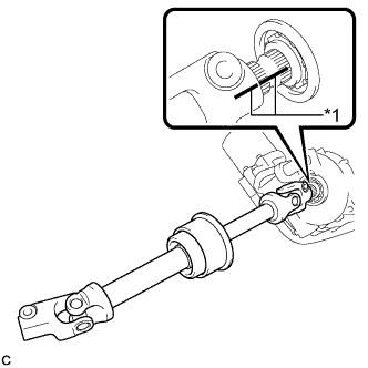
Text in Illustration *1 Matchmark Put matchmarks on the steering intermediate shaft assembly and the power steering link assembly.
-
Separate the steering intermediate shaft assembly from the power steering link assembly.
-
-
REMOVE STEERING POST ASSEMBLY
-
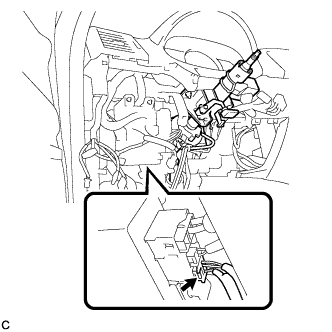
Disconnect the connector from the power steering ECU assembly.
-
Disconnect the connector from the power steering ECU assembly.
Tech Tips
Pull out the lock of the lock lever, disengage the claw, and raise the lock lever to disconnect the connector as shown in the illustration.
-
Disconnect the connectors and disengage the wire harness clamps from the steering post assembly.
-
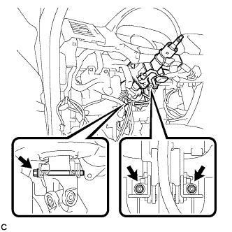
Remove the bolt, 2 nuts, and the steering post assembly.
-
-
REMOVE STEERING INTERMEDIATE SHAFT ASSEMBLY
-
Remove the bolt and slide the steering intermediate shaft assembly.
Note
Do not separate the steering intermediate shaft assembly from the steering column assembly.
-
Text in Illustration *1 Matchmark Put matchmarks on the steering intermediate shaft assembly and the steering column assembly.
-
Remove the steering intermediate shaft assembly from the steering column assembly.
-