STEERING LOCK SYSTEM Steering Lock Motor Drive Power Circuit
DESCRIPTION
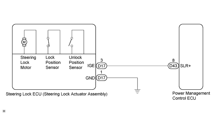
The steering lock ECU (steering lock actuator assembly) is connected to the power management control ECU. The steering lock ECU (steering lock actuator assembly) cannot activate the motor unless it receives permission signals from both ECUs. (The power management control ECU permits the steering lock ECU (steering lock actuator assembly) to supply power to activate the motor.)
WIRING DIAGRAM
INSPECTION PROCEDURE
PROCEDURE
-
CHECK VEHICLE CONDITION
-
Check the problem symptom of the steering lock system.
Result Condition Proceed to Steering lock cannot be released. A Steering cannot be locked. B
B 
INSPECT STEERING LOCK ECU (STEERING LOCK ACTUATOR ASSEMBLY) Click here
A 
-
-
READ VALUE USING GTS
-
Connect the GTS to the DLC3.
-
Turn the engine switch on (IG).
-
Turn the GTS on.
-
Check the steering lock command reception record. Enter the following menus: Body Electrical / Entry&Start / Data List.
Smart Key Tester Display Measurement Item/Range Normal Condition Diagnostic Note Lock/Unlock Receive Steering lock command reception record / Yes or No Yes: Steering lock/unlock signal received
No: Steering lock/unlock signal not received
- -
Check if steering unlock command reception is confirmed.
OK "YES" is displayed on the GTS.
NG 
CHECK SMART ENTRY AND START SYSTEM (for Start Function) Click here
OK
-
-
INSPECT STEERING LOCK ECU (STEERING LOCK ACTUATOR ASSEMBLY)
-
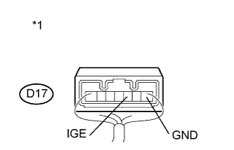
Text in Illustration *1 Component with harness connected
(Steering Lock ECU (Steering Lock Actuator Assembly))
Measure the voltage according to the value(s) in the table below.
Standard Voltage Tester Connection Condition Specified Condition D17-3 (IGE) - D17-1 (GND)
-
Turn the engine switch off
-
Turn the engine switch on (ACC or IG)
-
Motor activated: Below 1 V
-
Motor not activated:
10 to 12 V
-
NG
CHECK HARNESS AND CONNECTOR (STEERING LOCK ECU - BODY GROUND) Click here
OK 
PROCEED TO NEXT CIRCUIT INSPECTION SHOWN IN PROBLEM SYMPTOMS TABLE Click here
-
-
CHECK HARNESS AND CONNECTOR (STEERING LOCK ECU - BODY GROUND)
-
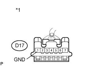
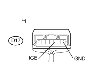
Text in Illustration *1 Front view of wire harness connector
(to Steering Lock ECU (Steering Lock Actuator Assembly))
Disconnect the D17 connector from the steering lock ECU (steering lock actuator assembly).
-
Measure the resistance according to the value(s) in the table below.
Standard Resistance Tester Connection Condition Specified Condition D17-1 (GND) - Body ground Always Below 1 Ω
NG
REPAIR OR REPLACE HARNESS OR CONNECTOR
OK
-
-
CHECK HARNESS AND CONNECTOR (STEERING LOCK ECU - POWER MANAGEMENT CONTROL ECU)
-
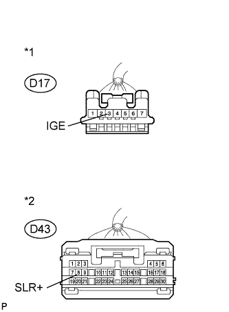
Text in Illustration *1 Front view of wire harness connector
(to Steering Lock ECU (Steering Lock Actuator Assembly))
*2 Front view of wire harness connector
(to Power Management Control ECU)
Disconnect the D43 connector from the power management control ECU.
-
Measure the resistance according to the value(s) in the table below.
Standard Resistance Tester Connection Condition Specified Condition D17-3 (IGE) - D43-8 (SLR+) Always Below 1 Ω D17-3 (IGE) - Body ground Always 10 kΩ or higher
NG
REPAIR OR REPLACE HARNESS OR CONNECTOR
OK
REPLACE POWER MANAGEMENT CONTROL ECU
-
-
INSPECT STEERING LOCK ECU (STEERING LOCK ACTUATOR ASSEMBLY)
-
Text in Illustration *1 Component with harness connected
(Steering Lock ECU (Steering Lock Actuator Assembly))
Measure the voltage according to the value(s) in the table below.
Standard Voltage Tester Connection Condition Specified Condition D17-3 (IGE) - D17-1 (GND) Specified condition is checked after performing the following:
-
Move the shift lever to P
-
Turn the engine switch off
-
Open the driver's door
-
Motor activated: Below 1 V
-
Motor not activated:
10 to 12 V
-
NG
CHECK HARNESS AND CONNECTOR (STEERING LOCK ECU - POWER MANAGEMENT CONTROL ECU) Click here
OK
PROCEED TO NEXT SUSPECTED AREA SHOWN IN PROBLEM SYMPTOMS TABLE Click here
-
-
CHECK HARNESS AND CONNECTOR (STEERING LOCK ECU - POWER MANAGEMENT CONTROL ECU)
-
Text in Illustration *1 Front view of wire harness connector
(to Steering Lock ECU (Steering Lock Actuator Assembly))
*2 Front view of wire harness connector
(to Power Management Control ECU)
Disconnect the D17 connector from the steering lock ECU (steering lock actuator assembly).
-
Disconnect the D43 connector from the power management control ECU.
-
Measure the resistance according to the value(s) in the table below.
Standard Resistance Tester Connection Condition Specified Condition D17-3 (IGE) - D43-8 (SLR+) Always Below 1 Ω D17-3 (IGE) - Body ground Always 10 kΩ or higher
NG
REPAIR OR REPLACE HARNESS OR CONNECTOR
OK
REPLACE POWER MANAGEMENT CONTROL ECU
-