STEERING LOCK SYSTEM, Diagnostic DTC:B2782

| DTC Code | DTC Name |
|---|---|
| B2782 | Power Source Control ECU Malfunction |
DESCRIPTION
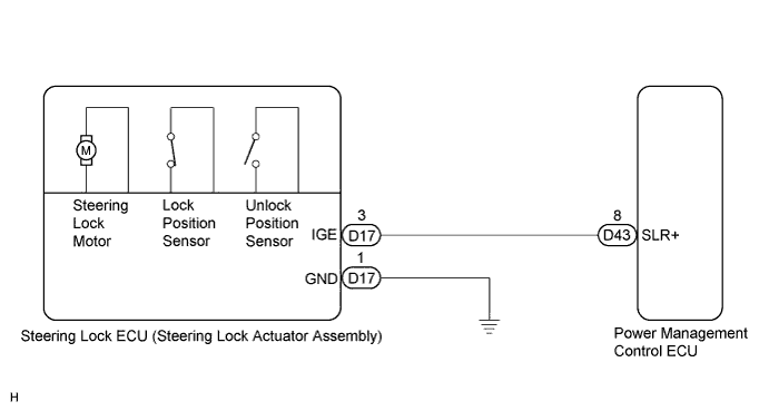
The power management control ECU controls the power supply to activate the steering lock motor. This prevents the steering wheel from being locked while the vehicle is moving.
| DTC No. | DTC Detecting Condition | Trouble Area |
|---|---|---|
| B2782 | Steering lock motor drive control circuit is defective. |
|
WIRING DIAGRAM
INSPECTION PROCEDURE
PROCEDURE
-
INSPECT STEERING LOCK ECU (STEERING LOCK ACTUATOR ASSEMBLY)
-
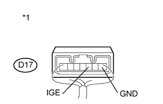
Text in Illustration *1 Component with harness connected
(Steering Lock ECU (Steering Lock Actuator Assembly))
Measure the voltage according to the value(s) in the table below.
Standard Voltage Tester Connection Condition Specified Condition D17-3 (IGE) - D17-1 (GND) Specified condition is checked after performing the following:
-
Turn the engine switch off
-
Turn the engine switch on (ACC or IG)
-
Motor activated: Below 1 V
-
Motor not activated: 10 to 12 V
D17-3 (IGE) - D17-1 (GND) Specified condition is checked after performing the following:
-
Move the shift lever to P
-
Turn the engine switch off
-
Open the driver's door
-
Motor activated: Below 1 V
-
Motor not activated: 10 to 12 V
Tech Tips
The steering lock ECU and steering lock actuator assembly are supplied as a single unit.
-
NG 
CHECK HARNESS AND CONNECTOR (STEERING LOCK ECU - BODY GROUND) Click here
OK 
REPLACE STEERING LOCK ECU (STEERING LOCK ACTUATOR ASSEMBLY) Click here
-
-
CHECK HARNESS AND CONNECTOR (STEERING LOCK ECU - BODY GROUND)
-
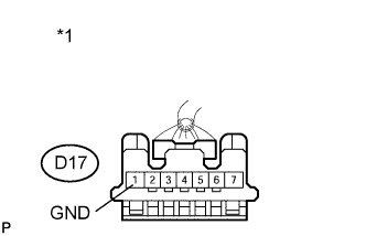
Text in Illustration *1 Front view of wire harness connector
(to Steering Lock ECU (Steering Lock Actuator Assembly))
Disconnect the D17 connector from the steering lock actuator assembly.
-
Measure the resistance according to the value(s) in the table below.
Standard Resistance Tester Connection Condition Specified Condition D17-1 (GND) - Body ground Always Below 1 Ω
NG 
REPAIR OR REPLACE HARNESS OR CONNECTOR
OK 
-
-
CHECK HARNESS AND CONNECTOR (STEERING LOCK ECU - POWER MANAGEMENT CONTROL ECU)
-
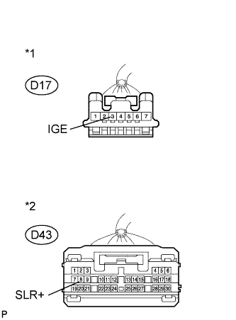
Text in Illustration *1 Front view of wire harness connector
(to Steering Lock ECU (Steering Lock Actuator Assembly))
*2 Front view of wire harness connector
(to Power Management Control ECU)
Disconnect the D43 connector from the power management control ECU.
-
Measure the resistance according to the value(s) in the table below.
Standard Resistance Tester Connection Condition Specified Condition D17-3 (IGE) - D43-8 (SLR+) Always Below 1 Ω D17-3 (IGE) - Body ground Always 10 kΩ or higher
NG
REPAIR OR REPLACE HARNESS OR CONNECTOR
OK
REPLACE POWER MANAGEMENT CONTROL ECU Click here
-