POWER STEERING SYSTEM PS Warning Light Remains ON
DESCRIPTION
If the power steering ECU detects a malfunction, the P/S warning light comes on. At this time, the power steering ECU stores a DTC in its memory.
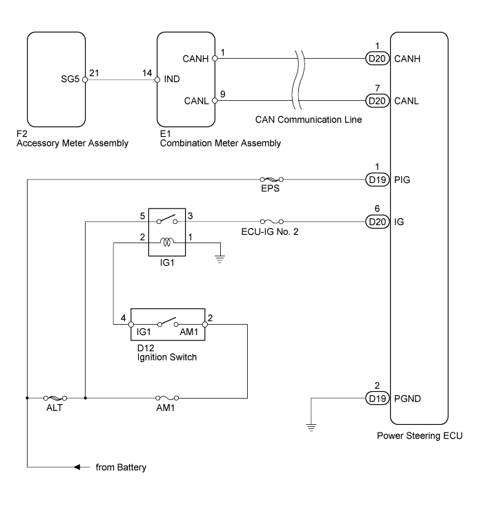
WIRING DIAGRAM
-
w/ Smart Entry and Start System

-
w/o Smart Entry and Start System
INSPECTION PROCEDURE
Note
If the power steering ECU has been replaced with a new one, perform the rotation angle sensor initialization and torque sensor zero point calibration Click here.
PROCEDURE
-
CHECK HARNESS AND CONNECTOR
-
Turn the ignition switch to ON.
-
Check the indication condition of the P/S warning light by wiggling the power steering ECU connector and wire harness up and down, and right and left.
OK P/S warning light indication condition does not change.
NG 
REPAIR OR REPLACE HARNESS OR CONNECTOR
OK 
-
-
CHECK FOR DTC (CAN COMMUNICATION SYSTEM)
-
Check for DTCs Click here.
OK DTC is not output.
NG
GO TO CAN COMMUNICATION SYSTEM Click here
OK
-
-
READ VALUE USING GTS (IG POWER SUPPLY)
-
Turn the ignition switch off.
-
Connect the GTS to the DLC3.
-
Turn the ignition switch to ON.
-
Turn the GTS on.
-
Enter the following menus: Chassis / EMPS / Data List.
-
Select the items "IG Power Supply" in the Data List and read the value displayed on the GTS.
EMPS Tester Display Measurement Item/Range Normal Condition Diagnostic Note IG Power Supply ECU power source voltage/
Min.: 0 V
Max.: 20.1531 V
11 to 14 V Ignition switch ON OK Normal condition value is displayed the GTS.
NG
INSPECT CHARGING SYSTEM Click here
OK
-
-
CHECK HARNESS AND CONNECTOR (POWER STEERING ECU - BODY GROUND)
-
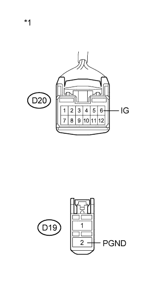
Text in Illustration *1 Front view of wire harness connector
(to Power Steering ECU)
Disconnect the connectors from the power steering ECU.
-
Measure the voltage according to the value(s) in the table below.
Standard Voltage Tester Connection Switch Condition Specified Condition D20-6 (IG) - Body ground Ignition switch ON 11 to 14 V -
Measure the resistance according to the value(s) in the table below.
Standard Resistance Tester Connection Condition Specified Condition D19-2 (PGND) - Body ground Always Below 1 Ω
NG
REPAIR OR REPLACE HARNESS OR CONNECTOR
OK
-
-
REPLACE POWER STEERING ECU
-
Replace the power steering ECU Click here.
-
Check the P/S warning light condition.
OK P/S warning light remains on when the ignition switch is ON and goes off after engine start.
NG
GO TO METER / GAUGE SYSTEM Click here
OK 
END
-