REAR BRAKE INSTALLATION

-
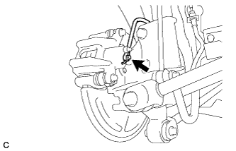
TEMPORARILY TIGHTEN REAR DISC BRAKE BLEEDER PLUG
-
Temporarily tighten the rear disc brake bleeder plug.
Tech Tips
Fully tighten the rear disc brake bleeder plug after bleeding any air left in the system.
-
Install the rear disc brake bleeder plug cap.
-
-
INSTALL REAR DISC
-
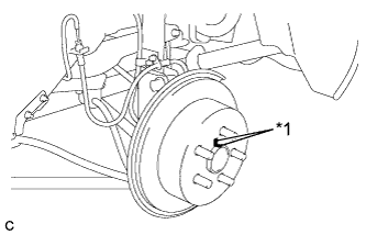
Text in Illustration *1 Matchmark Align the matchmarks of the rear disc and axle hub, and install the rear disc.
Note
When installing a new rear disc, select the installation position where the rear disc has minimal runout.
-
-
INSTALL PARKING BRAKE SHOE ADJUSTING HOLE PLUG
-
INSTALL REAR DISC BRAKE CYLINDER MOUNTING
-
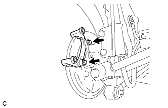
Install the rear disc brake cylinder mounting with the 2 bolts.
- Torque:
- 78 N*m { 800 kgf*cm, 58 ft.*lbf }
-
-
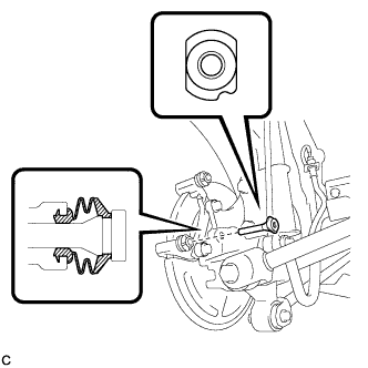
INSTALL REAR DISC BRAKE BUSHING DUST BOOT
-
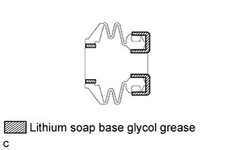
Apply a light layer of lithium soap base glycol grease to the seal surfaces of 2 new rear disc brake bushing dust boots.
Tech Tips
Apply at least 0.3 g (0.01 oz.) of lithium soap base glycol grease to each rear disc brake bushing dust boot.
-
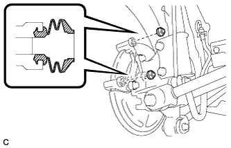
Install the 2 rear disc brake bushing dust boots to the rear disc brake cylinder mounting.
-
-
INSTALL NO. 2 REAR DISC BRAKE CYLINDER SLIDE PIN
-
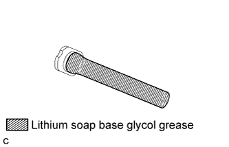
Apply a light layer of lithium soap base glycol grease to the sliding part and the seal surface of the No. 2 rear disc brake cylinder slide pin.
-
Install the No. 2 rear disc brake cylinder slide pin to the rear disc brake cylinder mounting.
-
Push the No. 2 rear disc brake cylinder slide pin into the rear disc brake bushing dust boot to align them.
-
-
INSTALL REAR DISC BRAKE CYLINDER SLIDE BUSHING
-
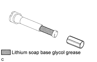
Apply a light layer of lithium soap base glycol grease to the contact surface of the No. 1 rear disc brake cylinder slide pin.
-
Install a new rear disc brake cylinder slide bushing to the No. 1 rear disc brake cylinder slide pin.
-
-
INSTALL NO. 1 REAR DISC BRAKE CYLINDER SLIDE PIN
-
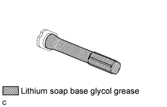
Apply a light layer of lithium soap base glycol grease to the sliding part and the seal surface of the No. 1 rear disc brake cylinder slide pin.
-
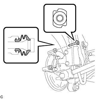
Install the No. 1 rear disc brake cylinder slide pin to the rear disc brake cylinder mounting.
-
Push the No. 1 rear disc brake cylinder slide pin into the rear disc brake bushing dust boot to align them.
-
-
INSTALL REAR DISC BRAKE PAD SUPPORT PLATE
-
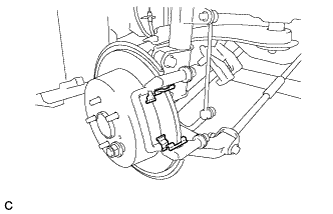
Install the 2 rear disc brake pad support plates to the rear disc brake cylinder mounting.
Note
Be sure to install the plates in the correct position and direction.
-
-
INSTALL REAR ANTI-SQUEAL SHIM
-
Install the rear anti-squeal shims to the 2 rear brake pads.
Note
-
When replacing worn pads, the rear anti-squeal shims must be replaced together with the pads.
-
Install the shims in the correct positions and directions.
-
-
-
INSTALL REAR DISC BRAKE PAD
-
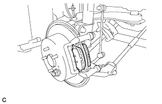
Install the 2 rear disc brake pads to the rear disc brake cylinder mounting.
Note
-
Make sure to install the rear disc brake pads with the pad wear indicator to the inner side of the vehicle.
-
There should be no oil or grease on the friction surfaces of the rear disc brake pads or the rear disc.
-
-
-
INSTALL REAR DISC BRAKE CYLINDER ASSEMBLY
-
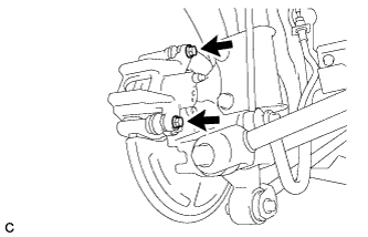
Install the rear disc brake cylinder assembly to the rear disc brake cylinder mounting with the 2 bolts.
- Torque:
- 32 N*m { 326 kgf*cm, 24 ft.*lbf }
-
-
CONNECT REAR FLEXIBLE HOSE
-
Connect the rear flexible hose to the rear disc brake cylinder assembly with a new union bolt and a new gasket.
- Torque:
- 29 N*m { 300 kgf*cm, 22 ft.*lbf }
Tech Tips
Install the rear flexible hose lock securely into the lock hole in the rear disc brake cylinder assembly.
-
-
FILL RESERVOIR WITH BRAKE FLUID
-
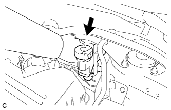
Remove the brake master cylinder reservoir filler cap.
-
Fill the reservoir with brake fluid.
Brake Fluid SAE J1703 or FMVSS No. 116 DOT 3 Note
-
Make sure that there is sufficient brake fluid in the reservoir.
-
Do not remove the filter from the brake master cylinder reservoir and be sure to fill with new brake fluid to avoid any potential contamination of the brake system. Contamination, for example by dirt particles or mineral oil, could lead to functional brake problem.
-
-
-
BLEED BRAKE LINE
Note
Bleed the brake line of the wheel farthest from the master cylinder first.
-
Connect a vinyl tube to the bleeder plug.
-
Depress the brake pedal several times, and while holding down the brake pedal, loosen the bleeder plug*1.
-
When fluid stops coming out, tighten the bleeder plug and release the brake pedal*2.
-
Repeat steps *1 and *2 until all the air in the brake fluid is completely bled out and the new brake fluid comes out.
-
Tighten the bleeder plug completely.
- Torque:
- 13 N*m { 133 kgf*cm, 10 ft.*lbf }
-
Repeat the above steps to replace the brake fluid of the brake lines for each wheel.
-
-
INSPECT FOR BRAKE FLUID LEAK
-
INSPECT FLUID LEVEL IN RESERVOIR
-
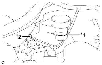
Text in Illustration *1 MAX Line *2 MIN Line Check the fluid level.
Tech Tips
If brake fluid level is lower than the MIN line, check for leaks and inspect the disc brake pads. If necessary, refill the reservoir with brake fluid to the MAX line after repair or replacement.
Brake Fluid SAE J1703 or FMVSS No. 116 DOT 3
-
-
ADJUST PARKING BRAKE
-
Completely release the parking brake pedal.
-
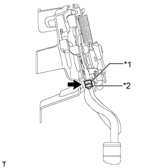
Text in Illustration *1 No. 1 wire adjusting nut *2 Lock nut Loosen the lock nut and No. 1 wire adjusting nut to completely release the parking brake cable.
-
Remove the rear wheel.
-
Temporarily install the 5 hub nuts.
-
Remove the shoe adjusting hole plug.
-
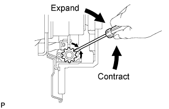
Turn the shoe adjuster and expand the shoe until the disc locks.
-
Turn and contract the shoe adjuster until the disc can rotate smoothly.
Standard Returns 8 notches. -
Check that there is no brake drag against the shoe.
-
Install the shoe adjusting hole plug.
-
Turn the adjusting nut until the parking brake pedal travel is corrected to be within the specified range.
Parking brake pedal travel 4 to 6 notches at 300 N (31 kgf, 67.5 lbf) -
Using a wrench or an equivalent tool, hold the adjusting nut and tighten the lock nut.
- Torque:
- 5.4 N*m { 55 kgf*cm, 48 in.*lbf }
-
Operate the parking brake pedal 3 to 4 times, and check the parking brake pedal travel.
-
Check that there is no brake drag against the shoe.
-
Remove the 5 hub nuts.
-
Install the rear wheel.
- Torque:
- 103 N*m { 1050 kgf*cm, 76 ft.*lbf }
-
-
INSTALL REAR WHEEL
- Torque:
- 103 N*m { 1050 kgf*cm, 76 ft.*lbf }