BRAKE BOOSTER INSTALLATION

-
INSTALL CHECK VALVE GROMMET
-
Install a new check valve grommet to the brake booster assembly.
-
-
INSTALL BRAKE VACUUM CHECK VALVE ASSEMBLY
-
Install the brake vacuum check valve assembly to the brake booster assembly.
-
-
INSTALL BRAKE MASTER CYLINDER PUSH ROD CLEVIS
-
Temporarily install the lock nut and brake master cylinder push rod clevis to the brake booster assembly.
-
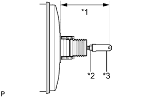
Text in Illustration *1 Push Rod Length *2 Lock Nut *3 Brake Master Cylinder Push Rod Clevis Set the push rod length as shown in the illustration.
Standard length*1 155.1 to 156.1 mm (6.11 to 6.15 in.) -
Tighten the lock nut.
- Torque:
- 26 N*m { 265 kgf*cm, 19 ft.*lbf }
-
-
INSTALL BRAKE BOOSTER GASKET
-
Install a new brake booster gasket to the brake booster assembly.
-
-
INSTALL BRAKE BOOSTER ASSEMBLY
-
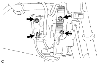
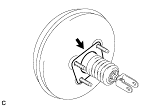
Install the brake booster assembly to the body with the 4 nuts.
- Torque:
- 13 N*m { 130 kgf*cm, 9 ft.*lbf }
Note
Do not damage the brake lines.
-
-
INSTALL PUSH ROD PIN
-
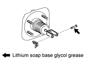
Apply lithium soap base glycol grease to the push rod pin.
-
Connect the brake master cylinder push rod clevis to the brake pedal sub-assembly, and install the push rod pin and a new clip as shown in the illustration.
-
-
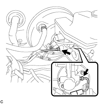
INSTALL NO. 1 VACUUM HOSE CONNECTOR
-
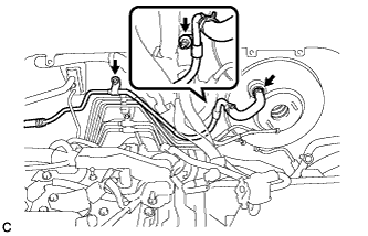
Install the No. 1 vacuum hose connector with the 2 nuts.
- Torque:
- 5.4 N*m { 55 kgf*cm, 48 in.*lbf }
-
Connect the vacuum hose to the brake booster assembly, and slide the clip to secure the vacuum hose.
-
-
INSTALL BRAKE MASTER CYLINDER SUB-ASSEMBLY
Note
When install a new brake master cylinder sub-assembly, remove the protectors from the piston and outlet ports.
-
Install a new O-ring to the brake master cylinder sub-assembly.
-
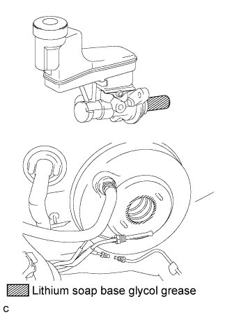
Apply a light layer of lithium soap base glycol grease to the entire circumference of the brake master cylinder sub-assembly and inner surface of the brake booster assembly as shown in the illustration.
-
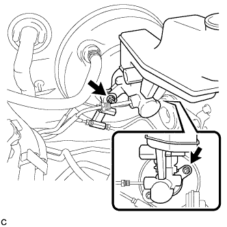
Install the brake master cylinder sub-assembly and front brake tube way with the 2 nuts.
- Torque:
- 13 N*m { 130 kgf*cm, 9 ft.*lbf }
Note
-
Do not kink or damage the brake line.
-
Do not allow brake line to twist and interfere with other parts or body during flexible hose tightening.
-
Do not allow any foreign matter such as dirt or dust to enter the brake line.
-
Using a union nut wrench, connect the 2 brake lines and install the No. 1 front brake tube to the brake master cylinder sub-assembly.
- Torque:
- 20 N*m { 199 kgf*cm, 14 ft.*lbf }
Note
-
Do not kink or damage the brake line.
-
Do not allow brake line to twist and interfere with other parts or body during flexible hose tightening.
-
Do not allow any foreign matter such as dirt or dust to enter the brake line.
-
Use the formula to calculate special torque values for situations where union nut wrench is combined with a torque wrench Click here.
-
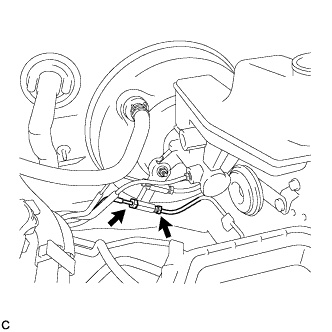
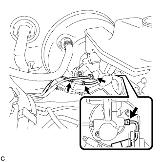
Using a union nut wrench, connect the 2 brake lines to the front brake tube way.
- Torque:
- 15 N*m { 155 kgf*cm, 11 ft.*lbf }
Note
-
Do not kink or damage the brake line.
-
Do not allow brake line to twist and interfere with other parts or body during flexible hose tightening.
-
Do not allow any foreign matter such as dirt or dust to enter the brake line.
-
Use the formula to calculate special torque values for situations where union nut wrench is combined with a torque wrench Click here.
-
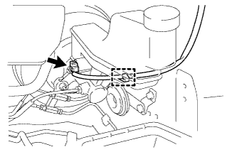
Connect the connector and engage the clamp.
-
-
FILL RESERVOIR WITH BRAKE FLUID
-
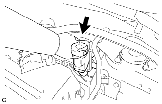
Remove the brake master cylinder reservoir filler cap.
-
Fill the reservoir with brake fluid.
Brake Fluid SAE J1703 or FMVSS No. 116 DOT 3 Note
-
Make sure that there is sufficient brake fluid in the reservoir.
-
Do not remove the filter from the brake master cylinder reservoir and be sure to fill with new brake fluid to avoid any potential contamination of the brake system. Contamination, for example by dirt particles or mineral oil, could lead to functional brake problem.
-
-
-
BLEED BRAKE MASTER CYLINDER
Note
-
To prevent brake fluid from damaging painted surfaces, cover any surrounding parts with a piece of cloth.
-
Be sure to clean your hands before bleeding from master cylinder to avoid any potential contamination of the brake system. Contamination, for example by dirt particles or mineral oil, could lead to functional brake problem.
Tech Tips
If the master cylinder is reinstalled or runs out of brake fluid, bleed the master cylinder.
-
Using a union nut wrench, disconnect the 2 brake tubes from the brake master cylinder assembly.
-
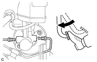
Slowly depress the brake pedal and hold it down.
-
Cover the 2 tube holes with your fingers and release the brake pedal.
-
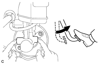
Uncover the holes, slowly depress the brake pedal and hold it down. While holding down the brake pedal, cover the tube holes again. Repeat this step 3 or 4 times.
-
Using a union nut wrench, connect the 2 brake tubes to the brake master cylinder assembly.
- Torque:
- 20 N*m { 199 kgf*cm, 14 ft.*lbf }
Note
-
Do not bend or damage the brake lines.
-
Do not allow brake line to twist and interfere with other parts or body during tightening.
-
Do not allow any foreign matter such as dirt or dust to enter the brake line.
-
Use the formula to calculate special torque values for situations where union nut wrench is combined with a torque wrench Click here.
-
-
BLEED BRAKE LINE
Note
Bleed the brake line of the wheel farthest from the master cylinder first.
-
Connect a vinyl tube to the bleeder plug.
-
Depress the brake pedal several times, and while holding down the brake pedal, loosen the bleeder plug*1.
-
When fluid stops coming out, tighten the bleeder plug and release the brake pedal*2.
-
Repeat steps *1 and *2 until all the air in the brake fluid is completely bled out and the new brake fluid comes out.
-
Tighten the bleeder plug completely.
- Torque:
- 13 N*m { 133 kgf*cm, 10 ft.*lbf }
-
Repeat the above steps to replace the brake fluid of the brake lines for each wheel.
-
-
INSPECT FOR BRAKE FLUID LEAK
-
INSPECT FLUID LEVEL IN RESERVOIR
-
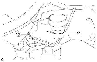
Text in Illustration *1 MAX Line *2 MIN Line Check the fluid level.
Tech Tips
If brake fluid level is lower than the MIN line, check for leaks and inspect the disc brake pads. If necessary, refill the reservoir with brake fluid to the MAX line after repair or replacement.
Brake Fluid SAE J1703 or FMVSS No. 116 DOT 3
-
-
INSPECT AND ADJUST BRAKE PEDAL
Tech Tips
-
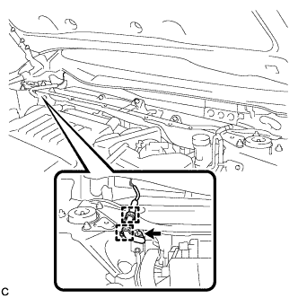
INSTALL SECURITY HORN ASSEMBLY (w/ Security Horn)
-
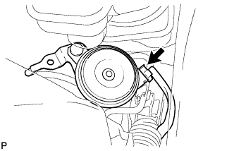
Connect the connector.
-
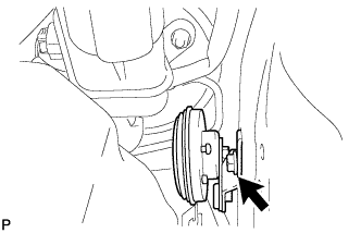
Install the security horn assembly with the bolt.
- Torque:
- 8.0 N*m { 82 kgf*cm, 71 in.*lbf }
-
-
INSTALL AIR CLEANER CASE SUB-ASSEMBLY
-
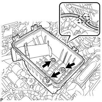
Install the air cleaner case sub-assembly with the 3 bolts.
- Torque:
- 5.0 N*m { 51 kgf*cm, 44 in.*lbf }
-
connect the wire harness clamp.
-
-
INSTALL AIR CLEANER FILTER ELEMENT SUB-ASSEMBLY
-
INSTALL AIR CLEANER CAP SUB-ASSEMBLY
-
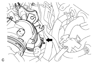
Connect the air-cleaner cap sub-assembly to the throttle body assembly and lock the hose band.
-
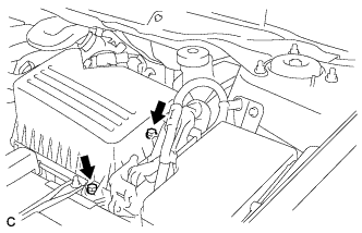
Install the air cleaner cap sub-assembly with the 2 bolts.
- Torque:
- 5.0 N*m { 51 kgf*cm, 44 in.*lbf }
-
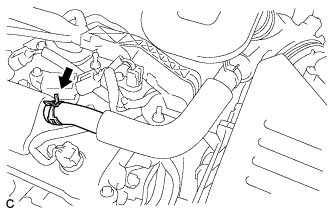
Connect the ventilation hose to the cylinder head cover.
-
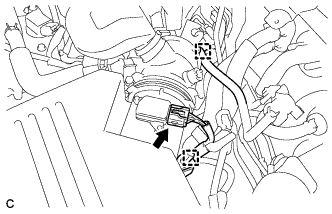
Connect the mass air flow meter connector and install the wire harness clamp to the air cleaner cap.
-
Install the hose to the hose clamp.
-
-
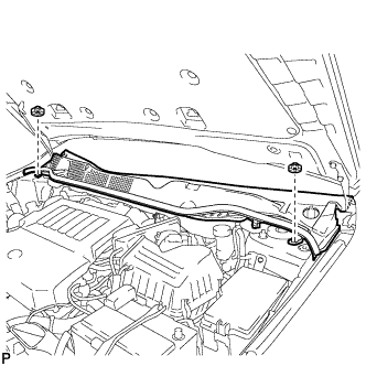
INSTALL OUTER COWL TOP PANEL
-
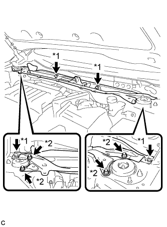
Text in Illustration *1 Bolt *2 Nut Install the outer cowl top panel with the 4 bolts and 4 nuts.
- Torque:
- Nut
- 85 N*m { 866 kgf*cm, 63 ft.*lbf }
- Bolt
- 8.8 N*m { 90 kgf*cm, 78 in.*lbf }
-
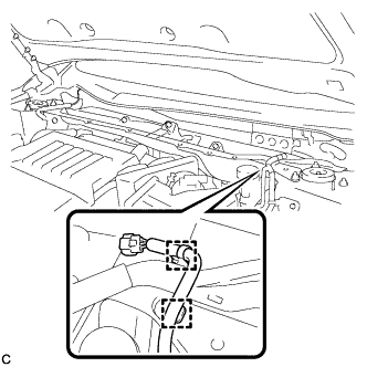
Engage the 2 wire harness clamps to the outer cowl top panel.
-
Engage the 2 wire harness clamps to the outer cowl top panel and connect the connector (w/ Windshield Deicer).
-
-
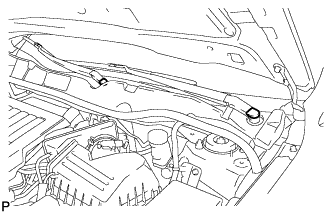
INSTALL WINDSHIELD WIPER MOTOR AND LINK ASSEMBLY
-
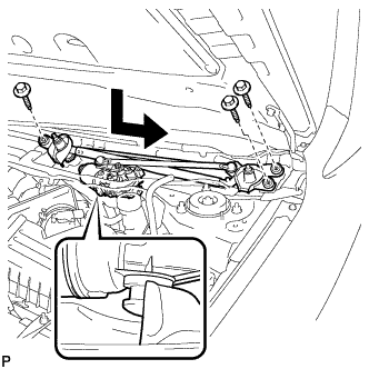
Install the windshield wiper motor and link assembly with the 3 bolts as shown in the illustration.
- Torque:
- 7.0 N*m { 71 kgf*cm, 62 in.*lbf }
-
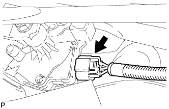
Connect the connector.
-
-
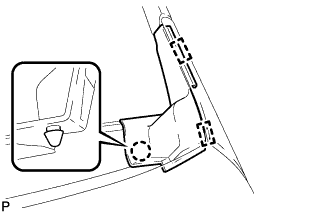
INSTALL COWL TOP VENTILATOR LOUVER SUB-ASSEMBLY
-
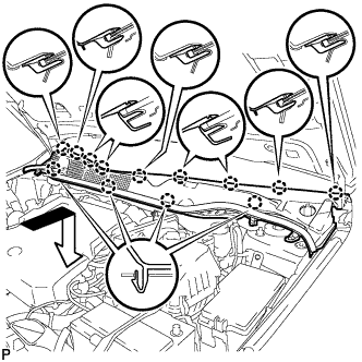
Engage the 13 claws and install the cowl top ventilator louver sub-assembly as shown in the illustration.
-
Install the 2 clips.
-
-
INSTALL FRONT FENDER TO COWL SIDE SEAL RH
Tech Tips
Use the same procedure for the RH side and LH side.
-
INSTALL FRONT FENDER TO COWL SIDE SEAL LH
-
Engage the claw and 2 guides to install the front fender to cowl side seal LH.
-
-
INSTALL FRONT WIPER ARM AND BLADE ASSEMBLY RH
-
Operate the wiper and stop the windshield wiper motor at the automatic stop position.
-
When reusing the front wiper arm and blade assembly RH:
-

Text in Illustration *1 Wiper Arm Serration Clean the wiper arm serrations.
-
-
When reusing the windshield wiper link assembly:
-
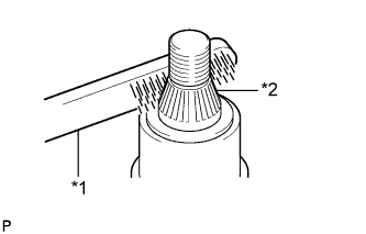
Text in Illustration *1 Wire Brush *2 Wiper Pivot Serration Clean the wiper pivot serrations with a wire brush.
-
-
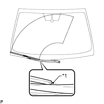
Text in Illustration *1 Ceramic Notch Install the front wiper arm and blade assembly RH with the nut to the position shown in the illustration.
- Torque:
- 20 N*m { 204 kgf*cm, 15 ft.*lbf }
-
-
INSTALL FRONT WIPER ARM AND BLADE ASSEMBLY LH
-
When reusing the front wiper arm and blade assembly LH:
-
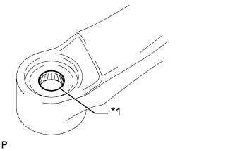
Text in Illustration *1 Wiper Arm Serration Clean the wiper arm serrations.
-
-
When reusing the windshield wiper link assembly:
-
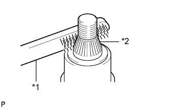
Text in Illustration *1 Wire Brush *2 Wiper Pivot Serration Clean the wiper pivot serrations with a wire brush.
-
-
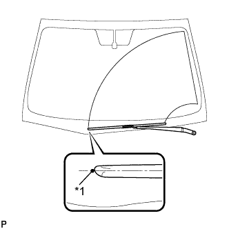
Text in Illustration *1 Ceramic Notch Install the front wiper arm and blade assembly LH with the nut to the position shown in the illustration.
- Torque:
- 20 N*m { 204 kgf*cm, 15 ft.*lbf }
-
Operate the front wipers while spraying washer fluid onto the windshield. Make sure that the front wipers function properly and the wipers do not come into contact with the vehicle body.
-
-
INSTALL FRONT WIPER ARM HEAD CAP
-
Install the 2 front wiper arm head caps.
-