BRAKE PEDAL INSTALLATION

-
INSTALL BRAKE PEDAL SUPPORT ASSEMBLY
-
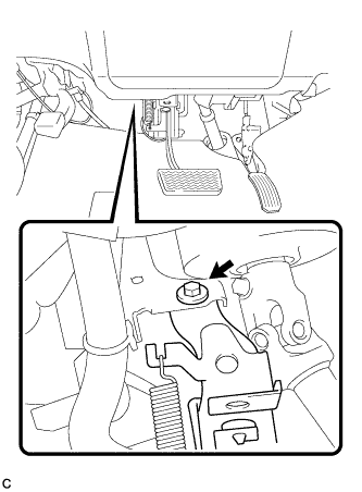
Install the brake pedal support assembly to the instrument panel reinforcement with the bolt.
- Torque:
- 19 N*m { 195 kgf*cm, 14 ft.*lbf }
-
Connect the connector.
-
-
INSTALL STOP LIGHT SWITCH MOUNTING ADJUSTER
-
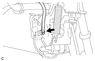
INSTALL STOP LIGHT SWITCH ASSEMBLY
-
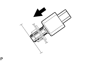
Insert the stop light switch assembly until the rod hits the pedal.
Note
When inserting the stop light switch assembly, support the pedal from behind so that the pedal is not depressed.
-
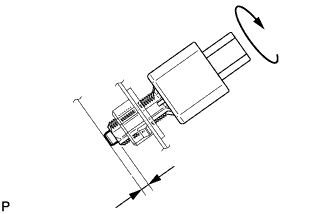
Make a quarter turn clockwise to install the stop light switch assembly.
- Torque:
- 1.5 N*m { 15 kgf*cm, 13 in.*lbf, or less }
Note
When inserting the stop light switch assembly, support the pedal from behind so that the pedal is not depressed.
-
Connect the connector.
-
Check the protrusion of the rod.
Protrusion of the rod 1.5 to 2.5 mm (0.0591 to 0.0984 in.) If the protrusion is not as specified, adjust it.
Note
Do not depress the brake pedal.
-
-
INSTALL HEADLIGHT LEVELING ECU ASSEMBLY
-
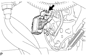
Install the headlight leveling ECU assembly with the bolt.
-
Connect the connector.
-
-
INSTALL BRAKE BOOSTER ASSEMBLY
Tech Tips
Refer to the instructions for Installation of the brake booster assembly Click here.