FRONT SPEED SENSOR REMOVAL

Tech Tips
-
Use the same procedure for the LH side and RH side.
-
The following procedure is for the LH side.
-
If the sensor rotor needs to be replaced, replace it together with the front drive shaft assembly.
-
DISCONNECT CABLE FROM NEGATIVE BATTERY TERMINAL
Note
When disconnecting the cable, some systems need to be initialized after the cable is reconnected Click here.
-
REMOVE FRONT WHEEL
-
REMOVE FRONT FENDER OUTSIDE MOULDING LH
-
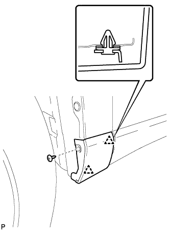
Remove the screw.
-
Disengage the 2 clips and remove the front fender outside moulding.
-
Remove the 2 clips (No. 1 outside moulding clip) from the front fender outside moulding.
-
-
REMOVE FRONT FENDER LINER LH
-
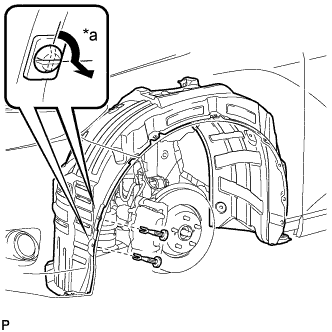
Text in Illustration *a 90° Using a screwdriver, turn the pin 90 degrees and remove the 2 pin hold clips.
-
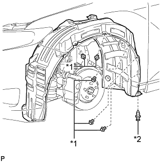
Text in Illustration *1 Clip <A> *2 Clip <B> Remove the 5 clips <A>.
-
Remove the clip <B>.
-
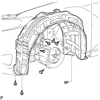
Remove the bolt and 6 screws.
-
Remove the grommet and front fender liner LH.
Tech Tips
The grommets need to be replaced with new ones because they will break when they are removed.
-
-
REMOVE FRONT SPEED SENSOR
-
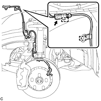
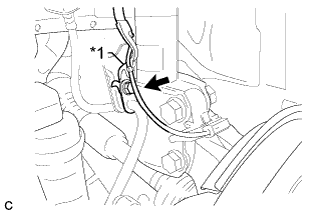
Disconnect the front speed sensor connector and remove the 2 clamps.
-
Text in Illustration *1 No. 2 Sensor Clamp Remove the bolt and No. 2 sensor clamp from the body.
-
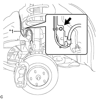
Text in Illustration *1 No. 1 Sensor Clamp Remove the bolt, No. 1 sensor clamp and flexible hose together from the shock absorber assembly.
-
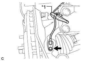
Text in Illustration *1 Resin Clamp Remove the bolt, resin clamp and front speed sensor.
Note
-
Prevent foreign matter from attaching to the front speed sensor tip.
-
Clean the speed sensor installation hole and the contact surfaces every time the front speed sensor is removed.
-
-