BRAKE ACTUATOR INSTALLATION

-
INSTALL BRAKE ACTUATOR ASSEMBLY
-
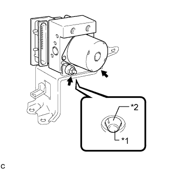
Text in Illustration *1 Pin *2 Cushion Install the brake actuator assembly to the brake actuator bracket assembly with the 2 nuts.
- Torque:
- 8.0 N*m { 82 kgf*cm, 71 in.*lbf }
Note
-
Do not remove the hole plugs of a new brake actuator before connecting the 6 brake lines because the brake actuator is filled with brake fluid.
-
Do not hold the actuator by the connector.
-
Set the actuator down with the pin being set securely as shown in the illustration.
-
-
INSTALL BRAKE ACTUATOR WITH BRACKET
-
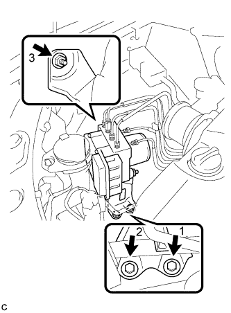
Install the brake actuator with bracket to the body with the nut and 2 bolts.
- Torque:
- 19 N*m { 194 kgf*cm, 14 ft.*lbf }
Note
-
Do not damage the brake lines or wire harness.
-
Tighten the nut and 2 bolts in order from 1 to 3.
-
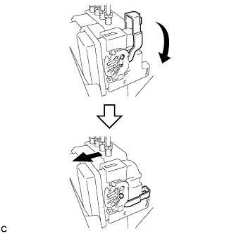
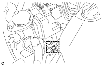
Connect the brake actuator connector.
Note
-
Make sure that the connector is locked securely.
-
Make sure that the actuator connector can be connected smoothly. Do not allow water, oil or dirt to enter.
-
-
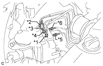
Text in Illustration *1 To front wheel cylinder RH *2 To front wheel cylinder LH *3 To rear wheel cylinder RH *4 To rear wheel cylinder LH *5 From 1st of master cylinder *6 From 2nd of master cylinder Temporarily tighten each brake line to the correct positions of the brake actuator with bracket as shown in the illustration.
-
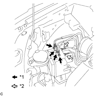
Text in Illustration *1 Flare Nut A (10 mm) *2 Flare Nut B (12 mm) Using union nut wrenches (10 mm and 12 mm), fully tighten each brake line.
- Torque:
- Flare nut A (10 mm)
- 15 N*m { 155 kgf*cm, 11 ft.*lbf }
- Flare nut B (12 mm)
- 20 N*m { 199 kgf*cm, 14 ft.*lbf }
Note
Use the formula to calculate special torque values for situations where a union nut wrench is combined with a torque wrench Click here.
-
Install the clamp of the suction hose sub-assembly to the brake actuator bracket assembly.
-
-
INSTALL RADIATOR RESERVE TANK ASSEMBLY
-
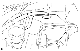
Install the radiator reserve tank assembly.
-
Install the radiator reserve tank cap assembly.
-
-
FILL RESERVOIR WITH BRAKE FLUID
-
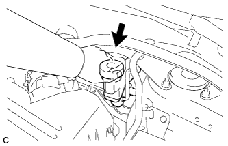
Remove the brake master cylinder reservoir filler cap.
-
Fill the reservoir with brake fluid.
Brake Fluid SAE J1703 or FMVSS No. 116 DOT 3 Note
-
Make sure that there is sufficient brake fluid in the reservoir.
-
Do not remove the filter from the brake master cylinder reservoir and be sure to fill with new brake fluid to avoid any potential contamination of the brake system. Contamination, for example by dirt particles or mineral oil, could lead to functional brake problem.
-
-
-
BLEED BRAKE MASTER CYLINDER
Note
-
To prevent brake fluid from damaging painted surfaces, cover any surrounding parts with a piece of cloth.
-
Be sure to clean your hands before bleeding from master cylinder to avoid any potential contamination of the brake system. Contamination, for example by dirt particles or mineral oil, could lead to functional brake problem.
Tech Tips
If the master cylinder is reinstalled or runs out of brake fluid, bleed the master cylinder.
-
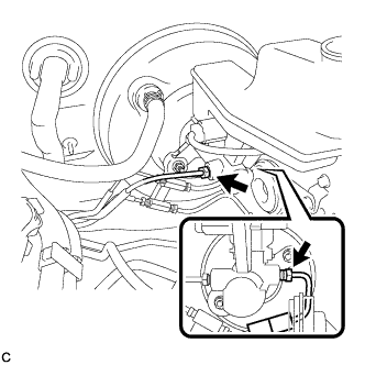
Using a union nut wrench, disconnect the 2 brake tubes from the brake master cylinder assembly.
-
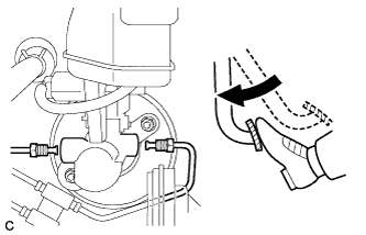
Slowly depress the brake pedal and hold it down.
-
Cover the 2 tube holes with your fingers and release the brake pedal.
-
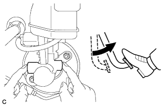
Uncover the holes, slowly depress the brake pedal and hold it down. While holding down the brake pedal, cover the tube holes again. Repeat this step 3 or 4 times.
-
Using a union nut wrench, connect the 2 brake tubes to the brake master cylinder assembly.
- Torque:
- 20 N*m { 199 kgf*cm, 14 ft.*lbf }
Note
-
Do not bend or damage the brake lines.
-
Do not allow brake line to twist and interfere with other parts or body during tightening.
-
Do not allow any foreign matter such as dirt or dust to enter the brake line.
-
Use the formula to calculate special torque values for situations where union nut wrench is combined with a torque wrench Click here.
-
-
BLEED BRAKE LINE
Note
Bleed the brake line of the wheel farthest from the master cylinder first.
-
Connect a vinyl tube to the bleeder plug.
-
Depress the brake pedal several times, and while holding down the brake pedal, loosen the bleeder plug*1.
-
When fluid stops coming out, tighten the bleeder plug and release the brake pedal*2.
-
Repeat steps *1 and *2 until all the air in the brake fluid is completely bled out and the new brake fluid comes out.
-
Tighten the bleeder plug completely.
- Torque:
- 13 N*m { 133 kgf*cm, 10 ft.*lbf }
-
Repeat the above steps to replace the brake fluid of the brake lines for each wheel.
-
-
INSPECT FLUID LEVEL IN RESERVOIR
-
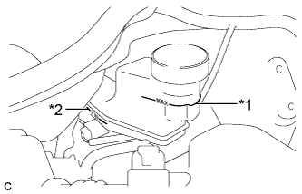
Text in Illustration *1 MAX Line *2 MIN Line Check the fluid level.
Tech Tips
If brake fluid level is lower than the MIN line, check for leaks and inspect the disc brake pads. If necessary, refill the reservoir with brake fluid to the MAX line after repair or replacement.
Brake Fluid SAE J1703 or FMVSS No. 116 DOT 3
-
-
INSPECT FOR BRAKE FLUID LEAK
-
CONNECT CABLE TO NEGATIVE BATTERY TERMINAL
Note
When disconnecting the cable, some systems need to be initialized after the cable is reconnected Click here.
-
PERFORM ENGINE VARIANT LEARNING
Tech Tips
-
INSPECT BRAKE ACTUATOR USING GTS
Tech Tips