VEHICLE STABILITY CONTROL SYSTEM, Diagnostic DTC:C1246/46, C1281/81

| DTC Code | DTC Name |
|---|---|
| C1246/46 | Master Cylinder Pressure Sensor Malfunction |
| C1281/81 | Master Cylinder Pressure Sensor Output Malfunction (Test Mode DTC) |
DESCRIPTION
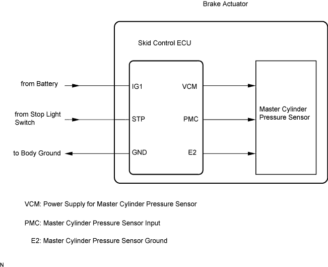
Master cylinder pressure sensor is connected to the skid control ECU in the brake actuator assembly.
DTC C1281/81 will be cleared when the master cylinder pressure sensor sends a master cylinder pressure signal or when Test Mode ends. DTC C1281/81 is output only in Test Mode.
| DTC Code | DTC Detection Condition | Trouble Area |
|---|---|---|
| C1246/46 | Any of the following is detected:
|
|
| C1281/81 | Detected only during Test Mode. |
|
WIRING DIAGRAM
Refer to DTC C1249/49 Click here.
INSPECTION PROCEDURE
PROCEDURE
-
CHECK STOP LIGHT OPERATION
-
Check that the stop light comes on when the brake pedal is depressed, and goes off when the brake pedal is released.
OK Condition Illumination Condition Brake pedal depressed ON Brake pedal released OFF
NG 
INSPECT STOP LIGHT CIRCUIT Click here
OK 
-
-
READ VALUE USING GTS (MASTER CYLINDER PRESSURE SENSOR)
-
Connect the GTS to the DLC3.
-
Start the engine.
-
Select the Data List on the GTS Click here.
ABS/VSC/TRC Tester Display Measurement Item/Range Normal Condition Diagnostic Note Master Cylinder Sensor Master cylinder pressure sensor reading / Min.: 0 V, Max.: 5 V Brake pedal released: 0.3 to 0.9 V Reading increases when brake pedal is depressed -
Check that the brake fluid pressure value of the master cylinder pressure sensor observed on the GTS changes when the brake pedal is depressed.
OK When the pedal is depressed, voltage displayed on the GTS increases.
NG
REPLACE BRAKE ACTUATOR ASSEMBLY Click here
OK
-
-
READ VALUE USING GTS (STOP LIGHT SWITCH)
-
Select the Data List on the GTS Click here.
ABS/VSC/TRC Tester Display Measurement Item/Range Normal Condition Diagnostic Note Stop Light SW Stop light switch / ON or OFF ON: Brake pedal depressed
OFF: Brake pedal released
- -
Check that the stop light condition observed on the GTS changes when the brake pedal is depressed.
OK When the brake pedal is depressed, the GTS displays "ON".
NG 
INSPECT SKID CONTROL ECU (STP TERMINAL) Click here
OK
-
-
RECONFIRM DTC
-
Turn the ignition switch off.
-
Clear the DTCs Click here.
-
Start the engine.
-
At a speed of 30 km/h (18 mph) or more, drive the vehicle and perform braking test (decelerate the vehicle by depressing the brake pedal).
-
Check if the same DTC is recorded Click here.
Result Result Proceed to DTC (C1246/46) is not output A DTC (C1246/46) is output B
B
REPLACE BRAKE ACTUATOR ASSEMBLY Click here
A 
CHECK FOR INTERMITTENT PROBLEMS Click here
-
-
INSPECT SKID CONTROL ECU (STP TERMINAL)
-
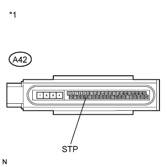
Text in Illustration *1 Front view of wire harness connector
(to Brake Actuator (Skid Control ECU))
Turn the ignition switch off.
-
Make sure that there is no looseness at the locking part and the connecting part of the connector.
-
Disconnect the skid control ECU connector.
-
Measure the voltage according to the value(s) in the table below.
Standard Voltage Tester Connection Switch Condition Specified Condition A42-30 (STP) - Body ground Stop light switch ON (Brake pedal depressed) 8 to 14 V A42-30 (STP) - Body ground Stop light switch OFF (Brake pedal released) Below 1.5 V
NG
REPAIR OR REPLACE HARNESS OR CONNECTOR (STP CIRCUIT)
OK
REPLACE BRAKE ACTUATOR ASSEMBLY Click here
-