VEHICLE STABILITY CONTROL SYSTEM, Diagnostic DTC:C1241/41

| DTC Code | DTC Name |
|---|---|
| C1241/41 | Low Battery Positive Voltage or Abnormally High Battery Positive Voltage |
DESCRIPTION
If a malfunction is detected in the power supply circuit, the skid control ECU (housed in the actuator assembly) stores this DTC and the fail-safe function prohibits ABS operation.
This DTC is stored when the IG1 terminal voltage deviates from the DTC detection condition due to a malfunction in the power supply or charging circuit such as the battery or alternator circuit, etc.
The DTC is canceled when the IG1 terminal voltage returns to normal.
| DTC Code | DTC Detection Condition | Trouble Area |
|---|---|---|
| C1241/41 | Any of the following is detected:
|
|
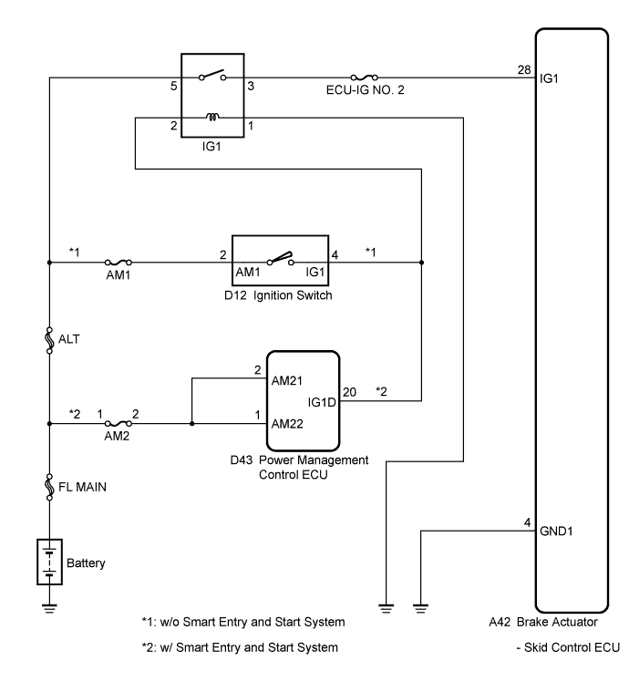
WIRING DIAGRAM
INSPECTION PROCEDURE
PROCEDURE
-
INSPECT ECU-IG NO. 2 FUSE
-
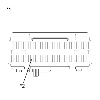
Text in Illustration *1 Main Body ECU (Driver Side Junction Block) *2 ECU-IG NO. 2 Fuse Remove the ECU-IG NO. 2 fuse from the main body ECU (driver side junction block).
-
Measure the resistance according to the value(s) in the table below.
Standard Resistance Tester Connection Condition Specified Condition ECU-IG NO. 2 (7.5 A) fuse Always Below 1 Ω
NG 
REPLACE ECU-IG NO. 2 FUSE
OK 
-
-
CHECK BATTERY
-
Install the ECU-IG NO. 2 fuse.
-
Check the battery voltage.
Standard Voltage 11 to 14 V
NG
CHECK OR REPLACE CHARGING SYSTEM OR BATTERY Click here
OK
-
-
INSPECT SKID CONTROL ECU (IG1 TERMINAL)
-
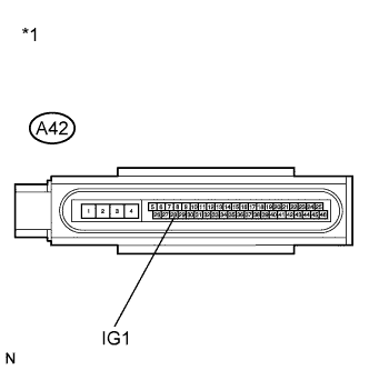
Text in Illustration *1 Front view of wire harness connector
(to Brake Actuator (Skid Control ECU))
Make sure that there is no looseness at the locking part and the connecting part of the connector.
-
Disconnect the skid control ECU connector.
-
Turn the ignition switch to ON.
-
Measure the voltage according to the value(s) in the table below.
Standard Voltage Tester Connection Switch Condition Specified Condition A42-28 (IG1) - Body ground Ignition switch ON 11 to 14 V
NG
REPAIR OR REPLACE HARNESS OR CONNECTOR (IG1 CIRCUIT)
OK
-
-
INSPECT SKID CONTROL ECU (GND1 TERMINAL)
-
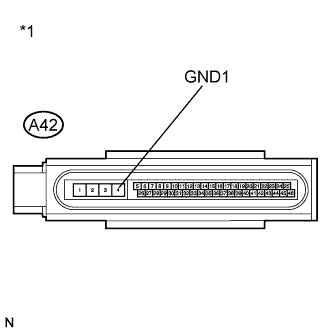
Text in Illustration *1 Front view of wire harness connector
(to Brake Actuator (Skid Control ECU))
Turn the ignition switch off.
-
Measure the resistance according to the value(s) in the table below.
Standard Resistance Tester Connection Condition Specified Condition A42-4 (GND1) - Body ground Always Below 1 Ω
NG
REPAIR OR REPLACE HARNESS OR CONNECTOR (GND1 CIRCUIT)
OK
-
-
RECONFIRM DTC
-
Reconnect the skid control ECU connector.
-
Clear the DTCs Click here.
-
Start the engine.
-
Perform a road test.
-
Check if the same DTC is recorded Click here.
Result Result Proceed to DTC (C1241/41) is not output A DTC (C1241/41) is output B Tech Tips
If troubleshooting has been carried out according to Problem Symptoms Table, refer back to the table and proceed to the next step Click here.
B
REPLACE BRAKE ACTUATOR ASSEMBLY Click here
A 
CHECK FOR INTERMITTENT PROBLEMS Click here
-