REAR SUSPENSION MEMBER (for AWD) INSTALLATION

-
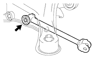
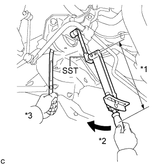
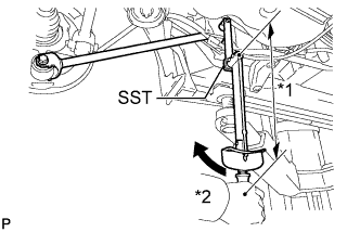
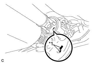
INSTALL STUD BOLT (for LH Side)
-
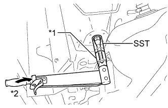
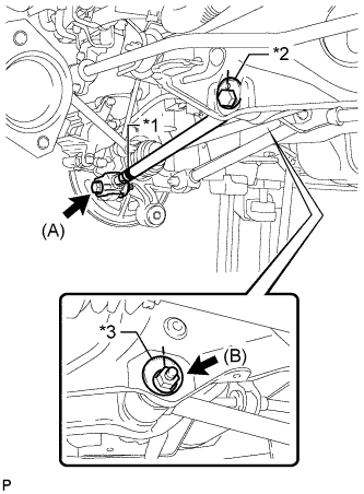
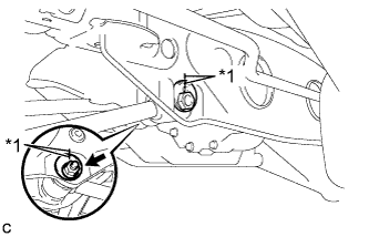
Text in Illustration *1 Socket Wrench *2 Turn Using SST and a socket wrench (21 mm), install the stud bolt.
- SST
- 09817-33190
- Torque:
- 180 N*m { 1839 kgf*cm, 133 ft.*lbf }
-
-
INSTALL STUD BOLT (for RH Side)
Tech Tips
Perform the same procedure as the LH side.
-
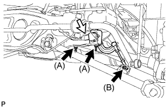
TEMPORARILY TIGHTEN REAR NO. 2 BODY MOUNTING BRACKET SUB-ASSEMBLY LH
-
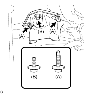
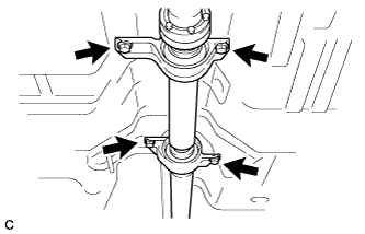
Temporarily install the rear No. 2 body mounting bracket sub-assembly LH with the 2 bolts (A) and bolt (B).
Note
Two types of bolts are used. Install each bolt to the correct position.
-
-
TEMPORARILY TIGHTEN REAR NO. 2 BODY MOUNTING BRACKET SUB-ASSEMBLY RH
Tech Tips
Perform the same procedure as the LH side.
-
INSTALL HOLE PLUG
-
Install the 6 hole plugs.
-
-
INSTALL REAR SUSPENSION MEMBER BODY MOUNTING FRONT CUSHION (for LH Side)
-
Temporarily install a new rear suspension member body mounting front cushion while confirming the installation direction.
-
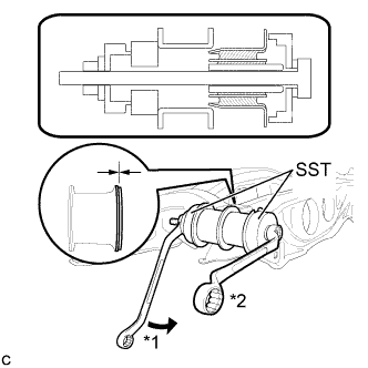
Using SST, install the rear suspension member body mounting front cushion until there is no clearance between the suspension member sub- assembly and the rear suspension member body mounting front cushion.
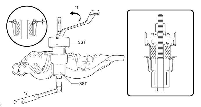
Text in Illustration *1 Turn *2 Hold - SST
- 09830-10010 ( 09830-01010, 09830-01020, 09830-01030, 09830-01060 )
Note
-
Tighten SST slowly and evenly.
-
Apply a small amount of grease to the threads of SST (center bolt) before use.
-
Install the side marked "F" of SST to the body mounting cushion.
-
-
INSTALL REAR SUSPENSION MEMBER BODY MOUNTING FRONT CUSHION (for RH Side)
Tech Tips
Perform the same procedure as the LH side.
-
INSTALL REAR SUSPENSION MEMBER BODY MOUNTING REAR CUSHION (for LH Side)
-
Temporarily install a new rear suspension member body mounting rear cushion while confirming the installation direction.
-
Text in Illustration *1 Turn *2 Hold Using SST, install the rear suspension member rear body mounting cushion until there is no clearance between the suspension member sub-assembly and the rear suspension member body mounting rear cushion.
- SST
- 09830-36010
- 09515-21010
Note
-
Tighten SST slowly and evenly.
-
Apply a small amount of grease to the threads of SST (center bolt) before use.
-
-
INSTALL REAR SUSPENSION MEMBER BODY MOUNTING REAR CUSHION (for RH Side)
Tech Tips
Perform the same procedure as the LH side.
-
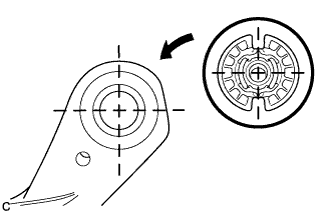
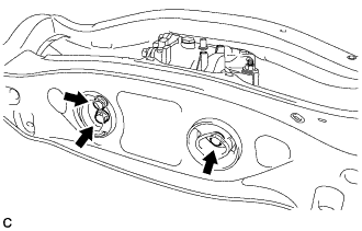
INSTALL REAR NO. 1 DIFFERENTIAL MOUNT CUSHION
-
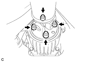
Using SST, install a new rear No. 1 differential mount cushion.
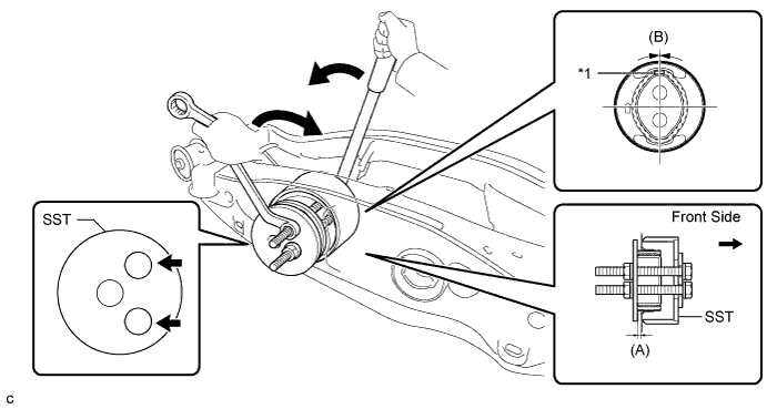
Text in Illustration *1 Protrusion - - - SST
- 09570-24011
(A) 5.0 to 6.0 mm (0.197 to 0.236 in.) (B) +/- 3° Note
-
Install the rear No. 1 differential mount cushion so that the protrusion is positioned upward.
-
Install the rear No. 1 differential mount cushion within +/- 3° from the center.
-
Temporarily install the rear No. 1 differential mount cushion to the rear suspension member before installing SST to prevent the rear No. 1 differential mount cushion from being tilted.
-
Apply grease to the threads of the SST bolts before use.
-
Be sure to use SST in the correct combination.
-
Do not set SST in the wrong direction.
-
Make sure that SST contacts the entire rear No. 1 differential mount cushion seating surface.
-
Do not slant the SST bolts.
-
Tighten the 2 SST bolts equally into the 2 rear No. 1 differential mount cushion holes.
-
-
INSTALL REAR NO. 2 DIFFERENTIAL MOUNT CUSHION
-
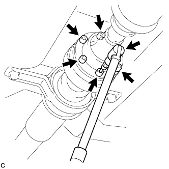
Using SST, install a new rear No. 2 differential mount cushion.
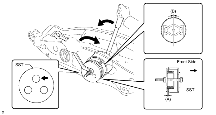
- SST
- 09570-24011
(A) 5.0 to 6.0 mm (0.197 to 0.236 in.) (B) +/- 3° Note
-
Install the rear No. 2 differential mount cushion within +/- 3° from the center.
-
Temporarily install the rear No. 2 differential mount cushion to the rear suspension member before installing SST to prevent the rear No. 2 differential mount cushion from being tilted.
-
Apply grease to the threads of the SST bolts before use.
-
Be sure to use SST in the correct combination.
-
Do not set SST in the wrong direction.
-
Make sure that SST contacts the entire rear No. 2 differential mount cushion seating surface.
-
Do not slant the SST bolts.
-
-
TEMPORARILY TIGHTEN REAR DIFFERENTIAL CARRIER ASSEMBLY WITH DIFFERENTIAL SUPPORT
-
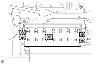
Temporarily install the rear differential carrier assembly with differential support to the rear side of the rear suspension member assembly with the 3 rear mounting bolts.
-
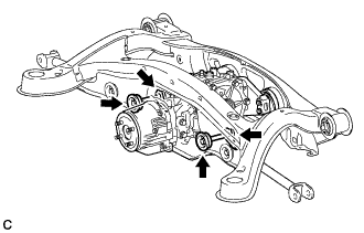
Temporarily install the rear differential carrier assembly with differential support to the front side of the rear suspension member assembly with the 2 bolts and 2 nuts.
Tech Tips
The nuts have tabs to prevent them from rotating.
-
-
FULLY TIGHTEN REAR DIFFERENTIAL CARRIER ASSEMBLY WITH DIFFERENTIAL SUPPORT
Note
Do not tighten the bolts with the inner cylinder or rear differential mount cushion tilted.
-
Install the rear differential carrier assembly with differential support to the rear side of the rear suspension member assembly with the 3 rear mounting bolts.
- Torque:
- 95 N*m { 970 kgf*cm, 70 ft.*lbf }
-
Install the rear differential carrier assembly with differential support to the front side of the rear suspension member assembly with the 2 bolts and 2 nuts.
- Torque:
- 114 N*m { 1162 kgf*cm, 84 ft.*lbf }
Tech Tips
The nuts have tabs to prevent them from rotating.
-
-
INSTALL REAR NO. 1 SUSPENSION ARM ASSEMBLY LH
-
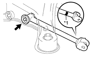
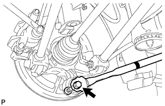
Text in Illustration *1 Identification Mark Temporarily install the rear No. 1 suspension arm assembly LH to the rear suspension member with the bolt and the nut.
Note
-
Ensure that the identification mark faces the rear side of the vehicle.
-
Since a stopper nut is used, temporarily tighten the bolt.
-
-
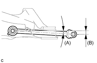
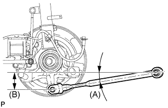
Set the rear No. 1 suspension arm assembly LH in the tightening position shown in the illustration.
Standard angle (A) 7°36' (7.6°) Standard length (B) 49.7 mm (1.96 in.) -
Fully tighten the bolt in the tightening position.
- Torque:
- 80 N*m { 816 kgf*cm, 59 ft.*lbf }
Note
Since a stopper nut is used, temporarily tighten the bolt.
-
-
INSTALL REAR NO. 1 SUSPENSION ARM ASSEMBLY RH
Tech Tips
Perform the same procedure as the LH side.
-
TEMPORARILY TIGHTEN REAR SUSPENSION MEMBER
-
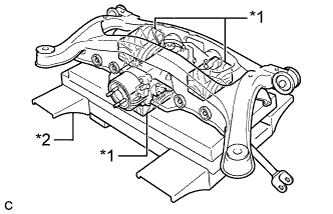
Text in Illustration *1 Wooden Block *2 Jack Support the rear suspension member using a jack and 3 wooden blocks as shown in the illustration.
Note
Support the rear suspension member until retightening of the suspension member is complete.
Tech Tips
Use properly sized wooden blocks to keep the jack and suspension member level.
-
Raise the rear suspension member using a jack with wooden blocks.
Note
When raising the rear suspension member, be careful not to damage the vehicle body or other components installed on the vehicle.
-
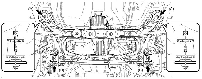
Temporarily install the rear suspension member, 2 rear upper suspension member stoppers and rear lower suspension member stopper retainers with the 2 nuts (A), 2 nuts (B) and 2 bolts.
Note
Be sure to install the rear suspension member with the rear upper suspension member stoppers and the rear lower suspension member stopper retainers in the correct direction shown in the illustration.
-
Fully tighten the 2 nuts (A).
- Torque:
- 115 N*m { 1173 kgf*cm, 85 ft.*lbf }
Tech Tips
Fully tighten the nut (B) after fully tightening the rear No. 2 body mounting bracket sub-assembly in the following steps.
-
-
FULLY TIGHTEN REAR NO. 2 BODY MOUNTING BRACKET SUB-ASSEMBLY LH
-
Lightly shake the rear suspension member to settle the body mounting cushion in the rear No. 2 body mounting bracket sub-assembly.
-
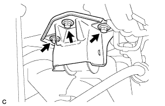
Fully tighten the 3 bolts.
- Torque:
- 90 N*m { 918 kgf*cm, 66 ft.*lbf }
-
-
FULLY TIGHTEN REAR NO. 2 BODY MOUNTING BRACKET SUB-ASSEMBLY RH
Tech Tips
Perform the same procedure as the LH side.
-
FULLY TIGHTEN REAR SUSPENSION MEMBER
-
Text in Illustration *1 Fulcrum Length *2 Turn *3 Hold Using SST and a socket wrench (19 mm), fully tighten the 2 nuts.
- SST
- 09961-00950
- Torque:
- without SST
- 96 N*m { 979 kgf*cm, 71 ft.*lbf }
- with SST
- 71 N*m { 724 kgf*cm, 52 ft.*lbf }
Note
-
Use a torque wrench with a fulcrum length of 425 mm (1.39 ft.).
-
This torque value is effective when SST is parallel to the torque wrench.
Tech Tips
Perform the same procedure for the RH side and LH side.
-
-
INSTALL FRAME WIRE
-
Engage the 6 clamps, connect the connector and the hose to install the frame wire.
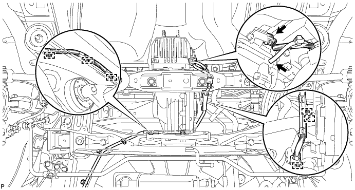
Note
Do not twist the frame wire when installing it.
-
-
INSTALL NO. 3 FLOOR WIRE
-
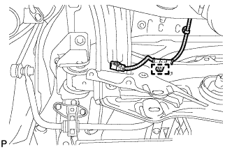
Engage the clamp to install the No. 3 floor wire.
Note
Do not twist the No. 3 floor wire when installing it.
-
-
INSTALL REAR DRIVE SHAFT SNAP RING LH
-
Install a new rear drive shaft snap ring.
-
-
INSTALL REAR DRIVE SHAFT ASSEMBLY LH
-
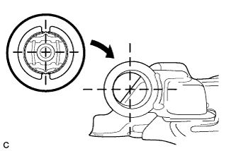
Text in Illustration *1 Matchmark Align the matchmarks and insert the rear drive shaft assembly to the rear axle assembly.
-
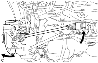
Text in Illustration *1 Rear Axle Assembly Insert the rear drive shaft assembly to the rear differential carrier assembly while pushing the rear axle assembly towards the outside of the vehicle.
Note
Do not disjoint inboard of the drive shaft.
-
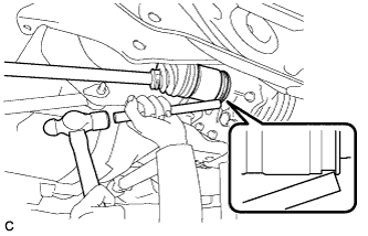
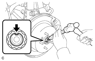
Using a brass bar and a hammer, engage the rear drive shaft assembly to the rear differential carrier assembly.
Note
-
Set the rear drive shaft snap ring with the opening facing downward.
-
Be careful not to damage the rear differential side gear shaft oil seal, rear drive shaft inboard joint boot and rear drive shaft dust cover.
-
Install the rear drive shaft assembly while keeping it level.
-
-
-
INSTALL REAR DRIVE SHAFT SNAP RING RH
Tech Tips
Perform the same procedure as the LH side.
-
INSTALL REAR DRIVE SHAFT ASSEMBLY RH
Tech Tips
Perform the same procedure as the LH side.
-
ADD DIFFERENTIAL OIL
-
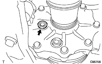
Remove the rear differential carrier cover plug.
-
Add differential oil Click here.
-
-
INSTALL REAR DIFFERENTIAL CARRIER COVER PLUG
-
Using a 10 mm hexagon wrench, install a new gasket and the rear differential carrier cover plug.
- Torque:
- 39 N*m { 398 kgf*cm, 29 ft.*lbf }
-
-
CONNECT REAR NO. 1 SUSPENSION ARM ASSEMBLY LH
-
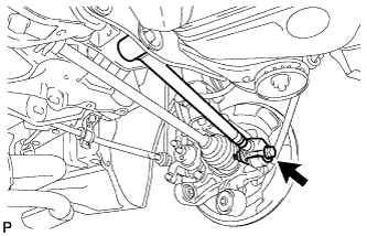
Connect the rear No. 1 suspension arm assembly LH to the rear axle carrier sub-assembly LH with the bolt and the nut.
- Torque:
- 112 N*m { 1142 kgf*cm, 83 ft.*lbf }
Note
Since a stopper nut is used, temporarily tighten the bolt.
-
-
CONNECT REAR NO. 1 SUSPENSION ARM ASSEMBLY RH
Tech Tips
Perform the same procedure as the LH side.
-
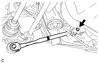
TEMPORARILY TIGHTEN REAR NO. 2 SUSPENSION ARM ASSEMBLY LH
-
Text in Illustration *1 Identification Mark *2 Rear Suspension Toe Adjust Cam Sub-assembly *3 No. 2 Camber Adjust Cam Temporarily tighten the rear No. 2 suspension arm assembly LH to the rear suspension member with the rear suspension toe adjust cam sub-assembly, the No. 2 camber adjust cam and the nut (B).
Note
Ensure that the identification mark faces the rear side of the vehicle.
Tech Tips
When temporarily tightening the nut, keep the rear suspension toe adjust cam sub-assembly from rotating.
-
Fully tighten the rear No. 2 suspension arm assembly LH to the rear axle carrier sub-assembly LH with the bolt (A) and the nut.
- Torque:
- 112 N*m { 1142 kgf*cm, 83 ft.*lbf }
Note
Since a stopper nut is used, fully tighten the bolt.
-
-
TEMPORARILY TIGHTEN REAR NO. 2 SUSPENSION ARM ASSEMBLY RH
Tech Tips
Perform the same procedure as the LH side.
-
INSTALL REAR STRUT ROD ASSEMBLY LH
-

Text in Illustration *1 Identification Mark Temporarily install the rear strut rod assembly to the rear axle carrier sub-assembly with the bolt and the nut.
Note
-
Ensure that the identification mark faces the inside of the vehicle.
-
Since a stopper nut is used, temporarily tighten the bolt.
-
-
Set the rear strut rod assembly in the tightening position shown in the illustration.
Standard angle (A) 9°3' (9.04°) Standard length (B) 78.3 mm (3.08 in.) -
Fully tighten the bolt in the tightening position.
- Torque:
- 80 N*m { 816 kgf*cm, 59 ft.*lbf }
-
Temporarily install the rear strut rod assembly to the body with the bolt and the nut.
-
Text in Illustration *1 Fulcrum Length *2 Turn Using SST and a socket wrench (17 mm), fully tighten the bolt in the rebound position.
- SST
- 09961-00950
- Torque:
- without SST
- 80 N*m { 816 kgf*cm, 59 ft.*lbf }
- with SST
- 59 N*m { 603 kgf*cm, 44 ft.*lbf }
Note
-
Since a stopper nut is used, fully tighten the bolt.
-
Use a torque wrench with a fulcrum length of 425 mm (1.39 ft.).
-
This torque value is effective when SST is parallel to the torque wrench.
-
-
INSTALL REAR STRUT ROD ASSEMBLY RH
Tech Tips
Perform the same procedure as the LH side.
-
INSTALL REAR HEIGHT CONTROL SENSOR SUB-ASSEMBLY
-
Install the rear height control sensor sub-assembly with the 3 nuts.
- Torque:
- Nut (A)
- 8.0 N*m { 82 kgf*cm, 71 in.*lbf }
- Nut (B)
- 5.4 N*m { 55 kgf*cm, 48 in.*lbf }
-
Connect the connector.
-
-
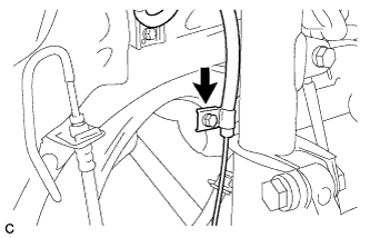
INSTALL NO. 3 PARKING BRAKE CABLE ASSEMBLY
-
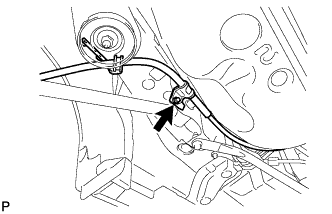
Install the No. 3 parking brake cable assembly with the bolt.
- Torque:
- 6.0 N*m { 61 kgf*cm, 53 in.*lbf }
-
Install the No. 3 parking brake cable assembly with the 2 nuts.
- Torque:
- 6.0 N*m { 61 kgf*cm, 53 in.*lbf }
-
-
INSTALL NO. 2 PARKING BRAKE CABLE ASSEMBLY
Tech Tips
Perform the same procedure as the No. 3 parking brake cable assembly.
-
INSTALL REAR AXLE SHAFT NUT LH
-
Clean the threaded parts on the drive shaft and axle shaft nut using a non-residue solvent.
Note
-
Be sure to perform this work for a new drive shaft.
-
Keep the threaded parts free of oil and foreign objects.
-
-
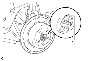
Install a new rear axle shaft nut.
- Torque:
- 294 N*m { 2998 kgf*cm, 217 ft.*lbf }
-
Using a chisel and hammer, stake the rear axle shaft nut.
-
-
INSTALL REAR AXLE SHAFT NUT RH
Tech Tips
Perform the same procedure as the LH side.
-
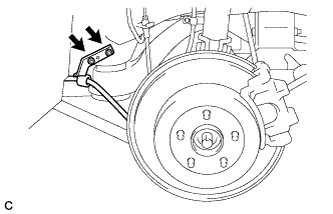
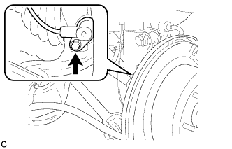
INSTALL REAR SPEED SENSOR LH
-
Install the rear speed sensor LH to the rear shock absorber with coil spring with the bolt.
- Torque:
- 8.0 N*m { 82 kgf*cm, 71 in.*lbf }
Note
Do not twist the rear speed sensor wire when installing it.
-
Install the rear speed sensor LH to the rear axle carrier sub-assembly with the bolt.
- Torque:
- 8.5 N*m { 87 kgf*cm, 75 in.*lbf }
Note
-
Keep the rear speed sensor tip and sensor installation hole free from foreign matter.
-
Do not twist the rear speed sensor wire when installing it.
-
-
INSTALL REAR SPEED SENSOR RH
Tech Tips
Perform the same procedure as the LH side.
-
TEMPORARILY TIGHTEN PROPELLER WITH CENTER BEARING SHAFT ASSEMBLY
-
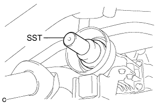
Remove SST from the transfer.
- SST
- 09325-20010
-
Install the propeller with center bearing shaft assembly.
Note
-
Be careful not to damage the oil seal.
-
Be careful not to damage the universal joint boot when installing the propeller shaft.
-
-
Text in Illustration *1 Matchmark Align the matchmarks on the rear propeller shaft and electromagnetic control coupling assembly and install the 4 nuts and 4 washers temporarily.
Note
Do not allow grease to adhere to be bolts or washers.
-
Temporarily install the propeller with center bearing shaft assembly with the 4 bolts, 2 No. 1 center support bearing washers and 2 No. 2 center support bearing washers.
Note
-
Reuse the washers.
-
Do not allow grease to adhere to be bolts or washers.
-
-
Fully tighten the 4 nuts.
- Torque:
- 37 N*m { 379 kgf*cm, 27 ft.*lbf }
-
-
FULLY TIGHTEN PROPELLER WITH CENTER BEARING SHAFT ASSEMBLY
- SST
- 09370-50010
-
Remove the piece of cloth or equivalent from the universal joint.
-
Depress the brake pedal and hold it.
-
Using a hexagon wrench (6 mm), tighten the 6 bolts.
- Torque:
- 26 N*m { 265 kgf*cm, 19 ft.*lbf }
-
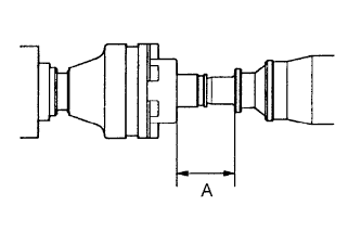
With the vehicle unloaded, adjust the dimension between the rear side of the cover and shaft as shown in the illustration.
Length A 65.5 to 70.5 mm (2.579 to 2.776 in.) -
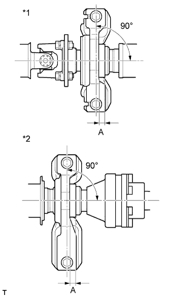
Text in Illustration *1 No. 1 Center Support Bearing Assembly *2 No. 2 Center Support Bearing Assembly With the vehicle unloaded, adjust the front and rear dimensions between the edge surface of the center support bearing and the edge surface of the cushion respectively as shown in the illustration, and then tighten the bolts.
Length A 11.5 to 13.5 mm (0.453 to 0.532 in.) -
Check that the center line of the bracket is at a right angle to the shaft axial direction.
-
Fully tighten the 4 bolts.
- Torque:
- 37 N*m { 375 kgf*cm, 27 ft.*lbf }
-
INSTALL NO. 1 FLOOR UNDER COVER
-
Install the No. 1 floor under cover with the 5 clips.
-
-
INSPECT AND ADJUST TRANSFER OIL
-
Inspect and adjust the transfer oil Click here.
-
-
INSTALL CENTER EXHAUST PIPE ASSEMBLY
-
Install the center exhaust pipe assembly.
Tech Tips
Refer to the instructions for Installation of the exhaust pipe Click here.
-
-
INSPECT FOR EXHAUST GAS LEAK
-
INSTALL REAR WHEELS
- Torque:
- 103 N*m { 1050 kgf*cm, 76 ft.*lbf }
-
STABILIZE SUSPENSION
-
Lower the vehicle to the ground.
-
Bounce the vehicle up and down at the corners to stabilize the rear suspension.
-
-
FULLY TIGHTEN REAR NO. 2 SUSPENSION ARM ASSEMBLY LH
-
Text in Illustration *1 Matchmark Align the matchmarks on the adjust cams and rear suspension member sub-assembly.
-
Fully tighten the nut.
- Torque:
- 100 N*m { 1020 kgf*cm, 74 ft.*lbf }
Note
The final torque must be applied under standard vehicle height conditions.
Tech Tips
When fully tightening the nut, keep the rear suspension toe adjust cam sub-assembly from rotating.
-
-
FULLY TIGHTEN REAR NO. 2 SUSPENSION ARM ASSEMBLY RH
Tech Tips
Perform the same procedure as the LH side.
-
INSPECT AND ADJUST REAR WHEEL ALIGNMENT
-
Inspect and adjust the rear wheel alignment Click here.
-
-
CHECK FOR SPEED SENSOR SIGNAL
-
Check for the speed sensor signal Click here.
-
-
HEIGHT CONTROL SENSOR SIGNAL INITIALIZATION
-
Initialize the height control sensor signal Click here.
-
-
INSPECT AND ADJUST HEADLIGHT AIMING
-
Inspect and adjust the headlight aiming Click here.
-