REAR SUSPENSION MEMBER (for AWD) REMOVAL

-
REMOVE REAR WHEELS
-
REMOVE CENTER EXHAUST PIPE ASSEMBLY
-
Remove the center exhaust pipe assembly.
Tech Tips
Refer to the instructions for Removal of the exhaust pipe Click here.
-
-
REMOVE PROPELLER WITH CENTER BEARING SHAFT ASSEMBLY
-
Depress the brake pedal and hold it.
-
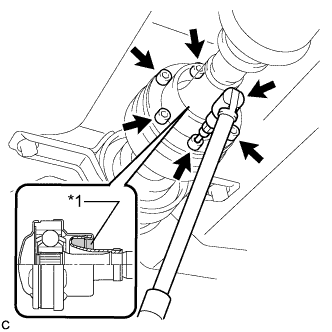
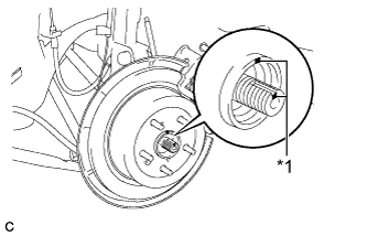
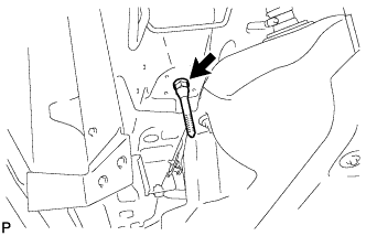
Text in Illustration *1 Piece of Cloth Using a hexagon wrench (6 mm), loosen the cross groove joint set bolts 1/2 turn.
Note
-
Put a piece of cloth or equivalent into the inside of the universal joint cover so that the boot does not touch the inside of the universal joint cover.
-
Do not remove the bolts.
-
-
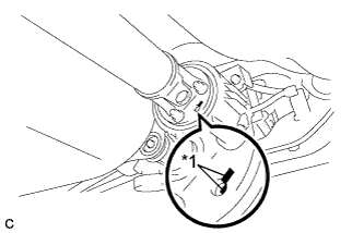
Text in Illustration *1 Matchmark Place matchmarks on the rear propeller shaft and electromagnetic control coupling assembly.
-
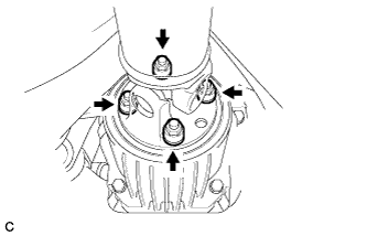
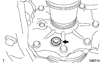
Remove the 4 nuts and 4 washers.
-
Using a brass bar and a hammer, separate the propeller with center bearing shaft assembly.
-
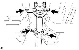
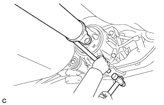
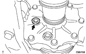
Remove the 4 bolts, 2 No. 1 center support bearing washers and 2 No. 2 center support bearing washers.
Note
When removing the bolts and washers, do not apply excessive force to the universal joint.
-
Pull out the propeller with center bearing shaft assembly from the transfer.
Note
-
When removing the propeller shaft, do not apply excessive force to the universal joint.
-
During and after the removal of the propeller shaft, keep the universal joint angle straight (within 15 degrees).
-
Be careful not to damage the oil seal.
-
-
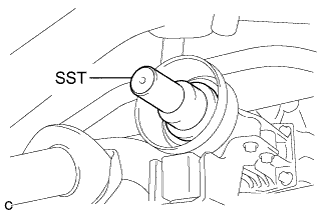
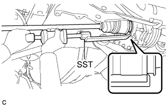
Insert SST into the transfer to prevent oil leaks.
- SST
- 09325-20010
Note
Be careful not to damage the oil seal.
-
-
SEPARATE REAR SPEED SENSOR LH
-
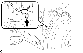
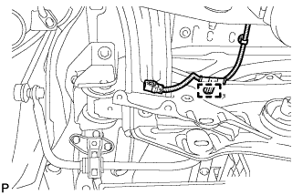
Remove the bolt and separate the rear speed sensor LH from the rear axle carrier sub-assembly.
Note
Keep the sensor tip and rear speed sensor installation hole free from foreign matter.
-
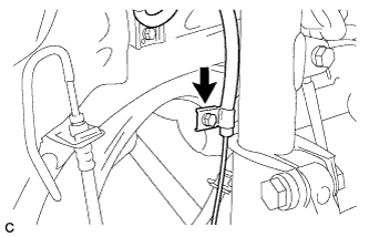
Remove the bolt and separate the rear speed sensor LH from the rear shock absorber with coil spring.
-
-
SEPARATE REAR SPEED SENSOR RH
Tech Tips
Perform the same procedure as the LH side.
-
REMOVE REAR AXLE SHAFT NUT LH
-
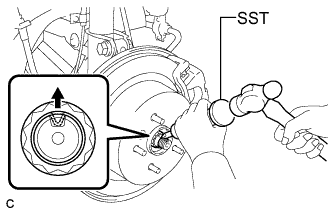
Using SST and a hammer, release the staked part of the rear axle shaft nut.
- SST
- 09930-00010
Note
Loosen the staked part of the nut completely, otherwise the threads of the drive shaft may be damaged.
-
While applying the brakes, remove the rear axle shaft nut.
-
-
REMOVE REAR AXLE SHAFT NUT RH
Tech Tips
Perform the same procedure as the LH side.
-
SEPARATE NO. 3 PARKING BRAKE CABLE ASSEMBLY
-
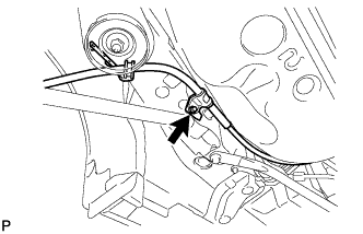
Remove the bolt and separate the No. 3 parking brake cable assembly.
-
Remove the 2 nuts and separate the No. 3 parking brake cable assembly.
-
-
SEPARATE NO. 2 PARKING BRAKE CABLE ASSEMBLY
Tech Tips
Perform the same procedure as the No. 3 parking brake cable assembly.
-
REMOVE NO. 1 FLOOR UNDER COVER
-
Separate the 5 clips to remove the No. 1 floor under cover.
Tech Tips
Remove the No. 1 floor under cover with the 5 clips.
-
-
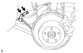
REMOVE REAR STRUT ROD ASSEMBLY LH
-
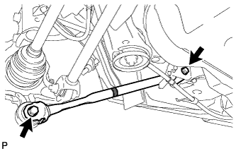
Remove the 2 bolts, the 2 nuts and the rear strut rod assembly.
Note
Since stopper nuts are used, loosen the bolts.
-
-
REMOVE REAR STRUT ROD ASSEMBLY RH
Tech Tips
Perform the same procedure as the LH side.
-
REMOVE REAR HEIGHT CONTROL SENSOR SUB-ASSEMBLY
-
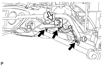
Disconnect the connector.
-
Remove the 3 nuts and rear height control sensor sub-assembly.
-
-
REMOVE REAR NO. 2 SUSPENSION ARM ASSEMBLY LH
-
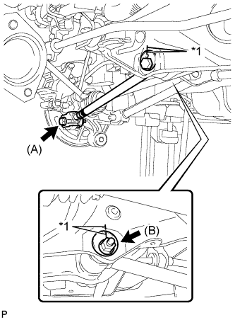
Text in Illustration *1 Matchmark Put matchmarks on the adjust cams and the rear suspension member sub-assembly.
-
Remove the bolt (A) and the nut, and separate the rear No. 2 suspension arm assembly LH from the rear axle carrier sub-assembly LH.
Note
Since a stopper nut is used, loosen the bolt.
-
Remove the nut (B), the No. 2 camber adjust cam, the rear suspension toe adjust cam sub-assembly, and the rear No. 2 suspension arm assembly LH.
Tech Tips
When removing the nut, keep the rear suspension toe adjust cam sub-assembly from rotating.
-
-
REMOVE REAR NO. 2 SUSPENSION ARM ASSEMBLY RH
Tech Tips
Perform the same procedure as the LH side.
-
SEPARATE REAR NO. 1 SUSPENSION ARM ASSEMBLY LH
-
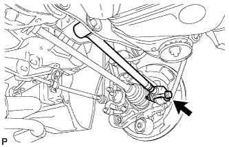
Remove the bolt and the nut, and separate the rear No. 1 suspension arm assembly LH from the rear axle carrier sub-assembly LH.
Note
Since a stopper nut is used, loosen the bolt.
-
-
SEPARATE REAR NO. 1 SUSPENSION ARM ASSEMBLY RH
Tech Tips
Perform the same procedure as the LH side.
-
DRAIN DIFFERENTIAL OIL
-
Using a hexagon wrench (10 mm), remove the rear differential carrier cover plug and gasket.
-
Using a hexagon wrench (10 mm), remove the rear differential drain plug and gasket, then drain the differential oil.
-
Using a hexagon wrench (10 mm), install the rear differential drain plug with a new gasket.
- Torque:
- 39 N*m { 398 kgf*cm, 29 ft.*lbf }
-
Using a hexagon wrench (10 mm), temporarily install the rear differential carrier cover plug.
Tech Tips
Add differential oil before installing a new gasket and fully tightening the rear differential carrier cover plug.
-
-
REMOVE REAR DRIVE SHAFT ASSEMBLY LH
-
Text in Illustration *1 Matchmark Put matchmarks on the rear drive shaft assembly and rear axle hub.
-
Using SST, disengage the rear drive shaft assembly from the rear differential carrier assembly.
- SST
- 09520-01010
- 09520-24010 ( 09520-32040 )
Note
Remove the rear drive shaft assembly while keeping it level.
-
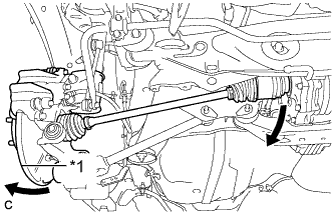
Text in Illustration *1 Rear Axle Assembly Separate the rear drive shaft assembly from the rear differential carrier assembly while pushing the rear axle assembly towards the outside of the vehicle.
Note
Do not disjoint inboard of the drive shaft.
-
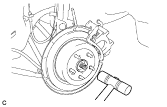
Using a plastic hammer, remove the rear drive shaft assembly from the rear axle assembly.
Note
Do not drop the rear drive shaft assembly.
-
-
REMOVE REAR DRIVE SHAFT SNAP RING LH
-
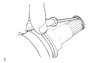
Using a screwdriver, remove the rear drive shaft snap ring.
-
-
REMOVE REAR DRIVE SHAFT ASSEMBLY RH
Tech Tips
Perform the same procedure as the LH side.
-
REMOVE REAR DRIVE SHAFT SNAP RING RH
Tech Tips
Perform the same procedure as the LH side.
-
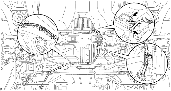
SEPARATE NO. 3 FLOOR WIRE
-
Disengage the clamp to separate the No. 3 floor wire from the rear suspension member.
-
-
SEPARATE FRAME WIRE
-
Disconnect the connector, separate the hose, and then disengage the 6 clamps to separate the frame wire.
-
-
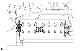
REMOVE REAR SUSPENSION MEMBER
-
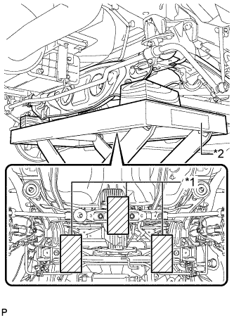
Text in Illustration *1 Wooden Block *2 Jack Support the rear suspension member with a jack using 3 wooden blocks as shown in the illustration.
Tech Tips
Use properly sized wooden blocks to keep the jack and suspension member level.
-
Remove the 4 nuts, 2 bolts and 2 rear lower suspension member stopper retainers.
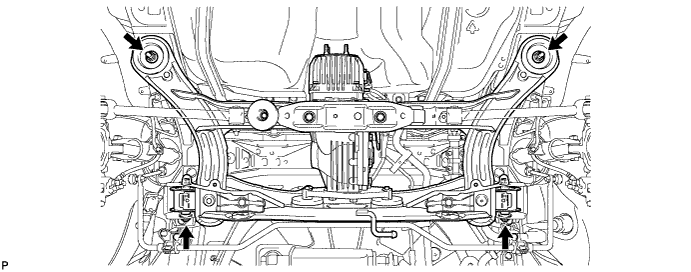
-
Lower the rear suspension member.
Note
When lowering the rear suspension member, be careful not to damage the vehicle body or other components installed on the vehicle.
-
Remove the 2 rear upper suspension member stoppers.
-
-
REMOVE REAR NO. 1 SUSPENSION ARM ASSEMBLY LH
-
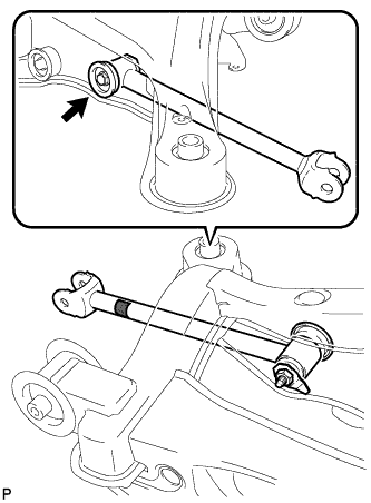
Remove the bolt, nut and rear No. 1 suspension arm assembly LH from the rear suspension member.
Note
Since a stopper nut is used, loosen the bolt.
-
-
REMOVE REAR NO. 1 SUSPENSION ARM ASSEMBLY RH
Tech Tips
Perform the same procedure as the LH side.
-
REMOVE REAR DIFFERENTIAL CARRIER ASSEMBLY WITH DIFFERENTIAL SUPPORT
-
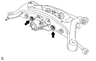
Remove the 2 bolts and 2 nuts.
Tech Tips
The nuts have tabs to prevent them from rotating.
-
Remove the 3 rear mounting bolts and rear differential carrier assembly with differential support from the rear suspension member.
-
-
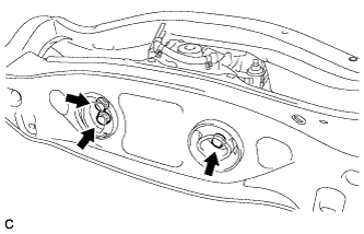
REMOVE REAR NO. 1 DIFFERENTIAL MOUNT CUSHION
-
Using SST, remove the rear No. 1 differential mount cushion.
- SST
- 09316-12010
- 09570-24011
Note
-
Do not bring SST into contact with the rear suspension member.
-
Do not slant the SST bolts.
-
Do not set SST in the wrong direction.
-
Tighten the 2 SST bolts equally into the 2 rear No. 1 differential mount cushion holes.
-
-
REMOVE REAR NO. 2 DIFFERENTIAL MOUNT CUSHION
-
Using SST, remove the rear No. 2 differential mount cushion.
- SST
- 09316-12010
- 09570-24011
Note
-
Do not bring SST into contact with the rear suspension member.
-
Do not slant the SST bolts.
-
Do not set SST in the wrong direction.
-
-
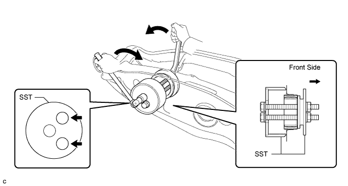
REMOVE REAR SUSPENSION MEMBER BODY MOUNTING FRONT CUSHION (for LH Side)
-
Using SST, remove the rear suspension member body mounting front cushion.
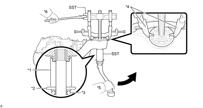
Text in Illustration *1 Spacer No. 1 *2 Washer *3 Bearing *4 Claw *5 Turn *6 Hold - SST
- 09830-10010 ( 09830-01010, 09830-01040, 09830-01050 )
- 09950-40011 ( 09951-04020, 09952-04010, 09954-04010, 09955-04011, 09958-04011 )
Note
-
Set the tips of the claws in the cutouts of the body mounting cushion.
-
Securely install the spacer No. 1 to the inner cylinder of the body mounting cushion as shown in the illustration.
-
Apply a small amount of grease to the threads of SST (center bolt) before use.
-
Tighten SST slowly and evenly.
-
Be careful as the body mounting cushion may fly out.
-
The body mounting cushion cannot be reused.
-
-
REMOVE REAR SUSPENSION MEMBER BODY MOUNTING FRONT CUSHION (for RH Side)
Tech Tips
Perform the same procedure as the LH side.
-
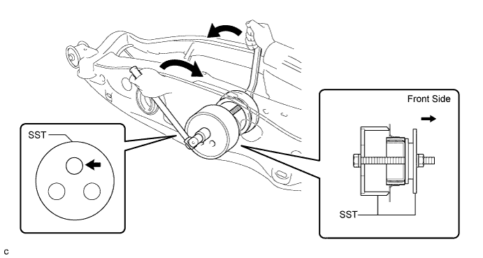
REMOVE REAR SUSPENSION MEMBER BODY MOUNTING REAR CUSHION (for LH Side)
-
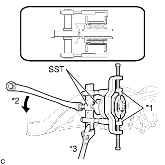
Text in Illustration *1 Claw *2 Turn *3 Hold Using SST, temporarily remove the rear suspension member body mounting rear cushion.
- SST
- 09710-30050
- 09950-40011 ( 09951-04020, 09952-04010, 09953-04010, 09954-04010, 09955-04031, 09958-04011 )
Note
-
Set the tips of the claws in the cutouts of the body mounting cushion.
-
Securely install the spacer No. 1 to the inner cylinder of the body mounting cushion as shown in the illustration.
-
Apply a small amount of grease to the threads of SST (center bolt) before use.
-
Tighten SST slowly and evenly.
-
Be careful as the body mounting cushion may fly out.
-
The body mounting cushion cannot be reused.
-
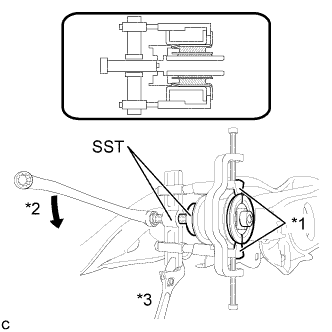
Text in Illustration *1 Claw *2 Turn *3 Hold When the mounting cushion protrudes approximately 6 mm, reassemble SST as shown in the illustration and remove the mounting cushion.
- SST
- 09710-30050
- 09950-40011 ( 09951-04020, 09952-04010, 09953-04010, 09953-04020, 09954-04010, 09955-04031, 09958-04011 )
Note
-
Set the tips of the claws in the cutouts of the body mounting cushion.
-
Securely install the spacer No. 1 to the inner cylinder of the body mounting cushion as shown in the illustration.
-
Apply a small amount of grease to the threads of SST (center bolt) before use.
-
Tighten SST slowly and evenly.
-
Be careful as the body mounting cushion may fly out.
-
The body mounting cushion cannot be reused.
Tech Tips
Use the shorter center bolt first, and then change it to the longer center bolt.
-
-
REMOVE REAR SUSPENSION MEMBER BODY MOUNTING REAR CUSHION (for RH Side)
Tech Tips
Perform the same procedure as the LH side.
-
REMOVE HOLE PLUG
-
Remove the 6 hole plugs.
-
-
REMOVE REAR NO. 2 BODY MOUNTING BRACKET SUB-ASSEMBLY LH
-
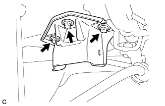
Remove the 3 bolts and rear No. 2 body mounting bracket sub-assembly LH.
-
-
REMOVE REAR NO. 2 BODY MOUNTING BRACKET SUB-ASSEMBLY RH
Tech Tips
Perform the same procedure as the LH side.
-
REMOVE STUD BOLT (for LH Side)
-
Remove the stud bolt.
-
-
REMOVE STUD BOLT (for RH Side)
Tech Tips
Perform the same procedure as the LH side.