REAR SUSPENSION MEMBER (for 2WD) INSTALLATION

-
INSTALL STUD BOLT (for LH Side)
-
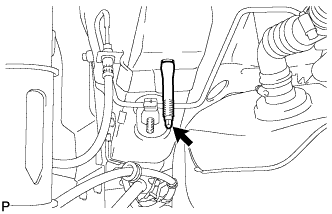
Install the stud bolt.
- Torque:
- 17 N*m { 173 kgf*cm, 13 ft.*lbf }
-
-
INSTALL STUD BOLT (for RH Side)
Tech Tips
Perform the same procedure as the LH side.
-
INSTALL HOLE PLUG
-
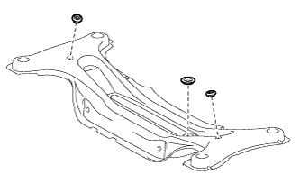
Install the hole plugs to the rear suspension member sub-assembly.
Tech Tips
There are 2 sizes of the hole plugs.
-
-
INSTALL REAR SUSPENSION MEMBER BODY MOUNTING FRONT CUSHION LH
-
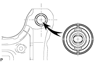
Temporarily install a new rear suspension member body mounting front cushion LH to the position shown in the illustration.
-
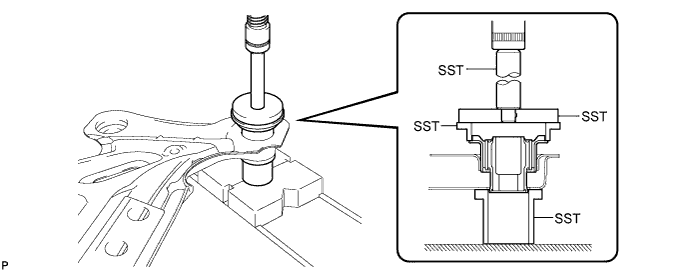
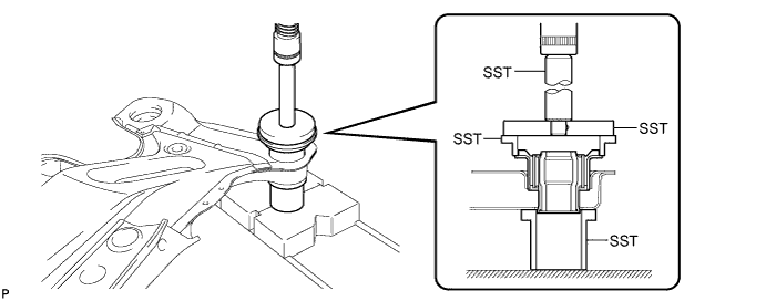
Using SST and a press, install the rear suspension member body mounting front cushion LH to the rear suspension member sub-assembly.
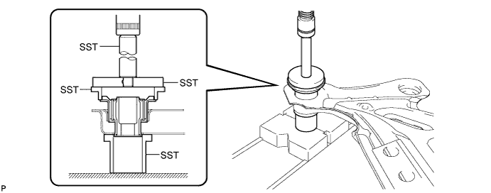
- SST
- 09502-12010
- 09515-30010
- 09950-60020 ( 09951-00890 )
- 09950-70010 ( 09951-07100 )
Tech Tips
Slowly press in the mounting cushion.
-
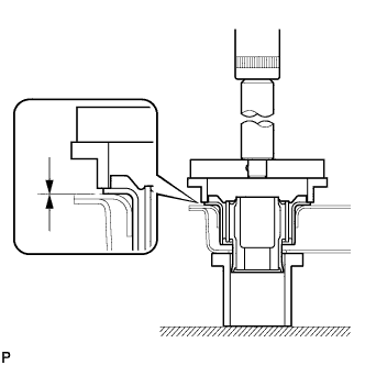
While observing from the side, press in the rear suspension member body mounting front cushion LH until there is no clearance between the rear suspension member body mounting front cushion LH and the rear suspension member sub-assembly as shown in the illustration.
Note
Do not press the rear suspension member excessively, or it will easily deform.
-
-
INSTALL REAR SUSPENSION MEMBER BODY MOUNTING FRONT CUSHION RH
-
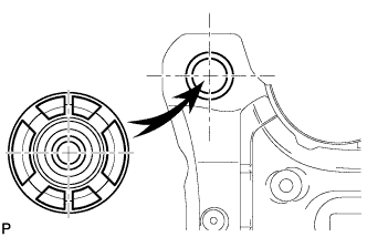
Temporarily install a new rear suspension member body mounting front cushion RH to the position shown in the illustration.
-
Using SST and a press, install the rear suspension member body mounting front cushion RH to the rear suspension member sub-assembly.
- SST
- 09502-12010
- 09515-30010
- 09950-60020 ( 09951-00890 )
- 09950-70010 ( 09951-07100 )
Tech Tips
Slowly press in the mounting cushion.
-
While observing from the side, press in the rear suspension member body mounting front cushion RH until there is no clearance between the rear suspension member body mounting front cushion RH and the rear suspension member sub-assembly as shown in the illustration.
Note
Do not press the rear suspension member excessively, or it will easily deform.
-
-
INSTALL REAR SUSPENSION MEMBER BODY MOUNTING REAR CUSHION (for LH Side)
-
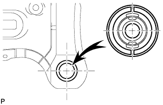
Temporarily install a new rear suspension member body mounting rear cushion (LH side) to the position shown in the illustration.
-
Using SST and a press, install the rear suspension member body mounting rear cushion (LH side) to the rear suspension member sub-assembly.
- SST
- 09502-12010
- 09515-30010
- 09950-60020 ( 09951-00890 )
- 09950-70010 ( 09951-07100 )
Tech Tips
Slowly press in the mounting cushion.
-
While observing from the side, press in the rear suspension member body mounting rear cushion (LH side) until there is no clearance between the rear suspension member body mounting rear cushion (LH side) and the rear suspension member sub-assembly as shown in the illustration.
Note
Do not press the rear suspension member excessively, or it will easily deform.
-
-
INSTALL REAR SUSPENSION MEMBER BODY MOUNTING REAR CUSHION (for RH Side)
Tech Tips
Perform the same procedure as the LH side.
-
INSTALL REAR SUSPENSION MEMBER
-
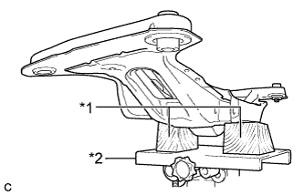
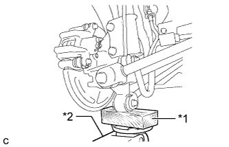
Text in Illustration *1 Wooden Block *2 Jack Support the rear suspension member using a jack and 2 wooden blocks as shown in the illustration.
Note
Make sure to secure the rear suspension member to prevent it from dropping.
Tech Tips
Use properly sized wooden blocks to keep the jack and suspension member level.
-
Raise the rear suspension member using a jack with wooden blocks.
Note
When raising the rear suspension member, be careful not to damage the vehicle body or other components installed on the vehicle.
-
Install the rear suspension member and rear lower suspension member stopper LH and rear lower suspension member stopper RH with the 4 nuts.
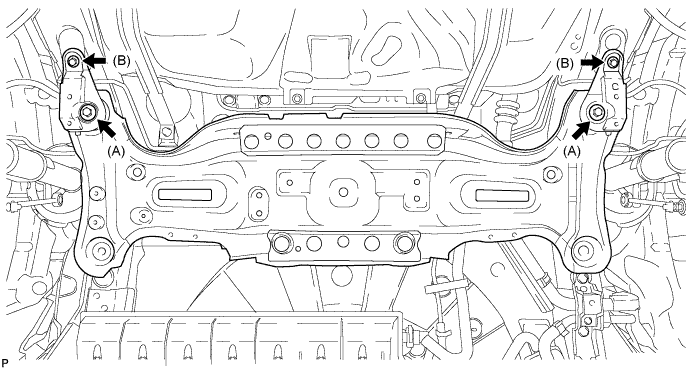
- Torque:
- Nut A
- 55 N*m { 561 kgf*cm, 41 ft.*lbf }
- Nut B
- 38 N*m { 387 kgf*cm, 28 ft.*lbf }
-
Install the rear suspension member and rear lower suspension member stoppers with the 2 bolts.
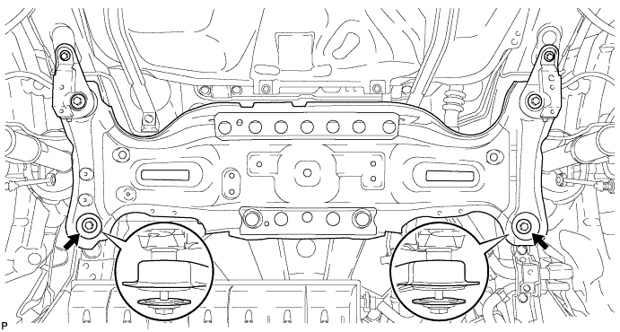
- Torque:
- 55 N*m { 561 kgf*cm, 41 ft.*lbf }
Note
Be sure to install the rear suspension member with the rear lower suspension member stoppers in the correct direction shown in the illustration.
-
-
TEMPORARILY INSTALL REAR NO. 1 SUSPENSION ARM ASSEMBLY LH
-
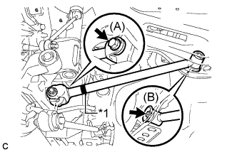
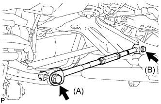
Text in Illustration *1 Identification Mark Temporarily install the rear No. 1 suspension arm assembly LH to the rear suspension member with the bolt (B).
Note
Ensure that the identification mark faces the rear side of the vehicle.
-
Temporarily install the rear No. 1 suspension arm assembly LH to the rear axle carrier sub-assembly with the bolt (A) and the nut.
Note
Since a stopper nut is used, temporarily tighten the bolt.
-
-
TEMPORARILY INSTALL REAR NO. 1 SUSPENSION ARM ASSEMBLY RH
Tech Tips
Perform the same procedure as the LH side.
-
TEMPORARILY INSTALL REAR NO. 2 SUSPENSION ARM ASSEMBLY LH
-
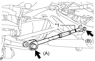
Text in Illustration *1 Identification Mark Temporarily install the rear No. 2 suspension arm assembly LH to the rear suspension member with the bolt (B).
Note
Ensure that the identification mark faces the rear side of the vehicle.
-
Temporarily install the rear No. 2 suspension arm assembly LH to the rear axle carrier sub-assembly LH with the bolt (A) and the nut.
Note
Since a stopper nut is used, temporarily tighten the bolt.
-
-
TEMPORARILY INSTALL REAR NO. 2 SUSPENSION ARM ASSEMBLY RH
-
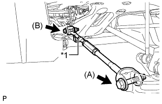
Text in Illustration *1 Identification Mark Temporarily install the rear No. 2 suspension arm assembly RH to the rear suspension member with the bolt (B).
Note
Ensure that the identification mark faces the rear side of the vehicle.
-
Temporarily install the rear No. 2 suspension arm assembly RH to the rear axle carrier sub-assembly RH with the bolt (B) and the nut.
Note
Since a stopper nut is used, temporarily tighten the bolt.
-
-
INSTALL LOWER NO. 1 EXHAUST PIPE SUPPORT BRACKET
-
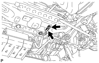
Install the lower No. 1 exhaust pipe support bracket with the 2 bolts.
- Torque:
- 33 N*m { 337 kgf*cm, 24 ft.*lbf }
-
-
INSTALL CENTER EXHAUST PIPE ASSEMBLY
-
Install the center exhaust pipe assembly.
Tech Tips
Refer to the instructions for Installation of the exhaust pipe Click here.
-
-
INSPECT FOR EXHAUST GAS LEAK
-
STABILIZE SUSPENSION
-
Install the rear wheels.
- Torque:
- 103 N*m { 1050 kgf*cm, 76 ft.*lbf }
-
Lower the vehicle to the ground.
-
Bounce the vehicle up and down at the corners to stabilize the rear suspension.
-
Remove the rear wheels.
-
-
FULLY TIGHTEN REAR NO. 1 SUSPENSION ARM ASSEMBLY LH
-
Text in Illustration *1 Wooden Block *2 Jack Support the rear axle carrier sub-assembly using a jack and wooden block as shown in the illustration.
Note
Do not bend the brake dust cover.
-
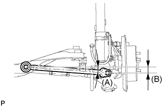
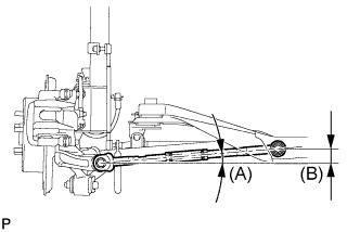
Jack up the rear axle carrier sub-assembly LH to set the rear No. 1 suspension arm assembly LH in the tightening position as shown in the illustration.
Standard angle (A) 4°36' (4.6°) Standard length (B) 38.6 mm (1.52 in.) CAUTION:
Do not jack up the rear axle carrier sub-assembly LH too high as the vehicle may fall.
Tech Tips
If the rear No. 1 suspension arm assembly LH cannot be positioned as shown in the illustration even when the rear axle carrier sub-assembly LH is jacked up, apply additional load to the vehicle such as by having a person sit in the rear seat.
-
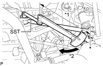
Using SST and a socket wrench (19 mm), fully tighten the bolt in the tightening position.
- SST
- 09961-00950
- Torque:
- without SST
- 120 N*m { 1224 kgf*cm, 89 ft.*lbf }
- with SST
- 89 N*m { 904 kgf*cm, 65 ft.*lbf }
Note
-
Use a torque wrench with a fulcrum length of 425 mm (1.39 ft.).
-
This torque value is effective when SST is parallel to the torque wrench.
-
Since a stopper nut is used, fully tighten the bolt.
-
Fully tighten the bolt in the tightening position.
- Torque:
- 112 N*m { 1142 kgf*cm, 83 ft.*lbf }
Note
Since a stopper nut is used, fully tighten the bolt.
-
-
FULLY TIGHTEN REAR NO. 1 SUSPENSION ARM ASSEMBLY RH
Tech Tips
Perform the same procedure as the LH side.
-
FULLY TIGHTEN REAR NO. 2 SUSPENSION ARM ASSEMBLY LH
-
Text in Illustration *1 Wooden Block *2 Jack Support the rear axle carrier sub-assembly using a jack and wooden block as shown in the illustration.
Note
Do not bend the brake dust cover.
-
Jack up the rear axle carrier sub-assembly LH to set the rear No. 2 suspension arm assembly LH in the tightening position as shown in the illustration.
Standard angle (A) 4°36' (4.6°) Standard length (B) 39.1 mm (1.54 in.) CAUTION:
Do not jack up the rear axle carrier sub-assembly LH too high as the vehicle may fall.
Tech Tips
If the rear No. 2 suspension arm assembly LH cannot be positioned as shown in the illustration even when the rear axle carrier sub-assembly LH is jacked up, apply additional load to the vehicle such as by having a person sit in the rear seat.
-
Fully tighten the bolts in the tightening position.
- Torque:
- Bolt (A)
- 112 N*m { 1142 kgf*cm, 83 ft.*lbf }
- Bolt (B)
- 120 N*m { 1224 kgf*cm, 89 ft.*lbf }
Note
Since a stopper nut is used, fully tighten the bolt (A) and (B).
-
-
FULLY TIGHTEN REAR NO. 2 SUSPENSION ARM ASSEMBLY RH
Tech Tips
Perform the same procedure as the LH side.
-
INSTALL REAR HEIGHT CONTROL SENSOR SUB-ASSEMBLY
-
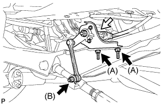
Install the rear height control sensor sub-assembly with the 3 nuts.
- Torque:
- Nut (A)
- 8.0 N*m { 82 kgf*cm, 71 in.*lbf }
- Nut (B)
- 5.4 N*m { 55 kgf*cm, 48 in.*lbf }
-
Connect the connector.
-
-
INSTALL REAR STABILIZER BAR
-
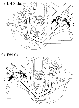
Install the rear stabilizer bar with the 4 bolts in order 1 to 2.
- Torque:
- 19 N*m { 194 kgf*cm, 14 ft.*lbf }
-
-
INSTALL REAR STABILIZER LINK ASSEMBLY LH
-

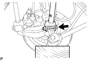
Text in Illustration *1 Turn *2 Hold Install the rear stabilizer link assembly LH to the rear stabilizer bar with the nut.
- Torque:
- 39 N*m { 400 kgf*cm, 29 ft.*lbf }
Tech Tips
If the ball joint turns together with the nut, use a hexagon wrench (5 mm) to hold the stud bolt.
-
-
INSTALL REAR STABILIZER LINK ASSEMBLY RH
Tech Tips
Perform the same procedure as the LH side.
-
INSTALL REAR WHEELS
- Torque:
- 103 N*m { 1050 kgf*cm, 76 ft.*lbf }
-
INSPECT AND ADJUST REAR WHEEL ALIGNMENT
-
Inspect and adjust the rear wheel alignment Click here.
-
-
HEIGHT CONTROL SENSOR SIGNAL INITIALIZATION
-
Initialize the height control sensor signal Click here.
-
-
INSPECT AND ADJUST HEADLIGHT AIMING
-
Inspect and adjust the headlight aiming Click here.
-