REAR LOWER ARM (for AWD) REMOVAL

-
REMOVE REAR WHEELS
-
REMOVE CENTER EXHAUST PIPE ASSEMBLY
-
Remove the center exhaust pipe assembly.
Tech Tips
Refer to the instructions for Removal of the exhaust pipe Click here.
-
-
REMOVE PROPELLER WITH CENTER BEARING SHAFT ASSEMBLY
-
Depress the brake pedal and hold it.
-
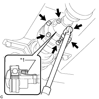
Text in Illustration *1 Piece of Cloth Using a hexagon wrench (6 mm), loosen the cross groove joint set bolts 1/2 turn.
Note
-
Put a piece of cloth or equivalent into the inside of the universal joint cover so that the boot does not touch the inside of the universal joint cover.
-
Do not remove the bolts.
-
-
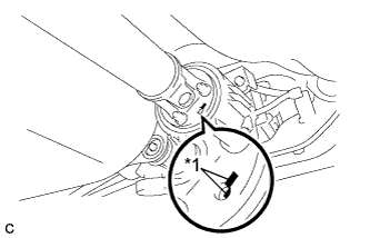
Text in Illustration *1 Matchmark Place matchmarks on the rear propeller shaft and electromagnetic control coupling assembly.
-
Remove the 4 nuts and 4 washers.
-
Using a brass bar and a hammer, separate the propeller with center bearing shaft assembly.
-
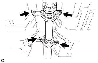
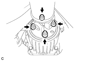
Remove the 4 bolts, 2 No. 1 center support bearing washers and 2 No. 2 center support bearing washers.
Note
When removing the bolts and washers, do not apply excessive force to the universal joint.
-
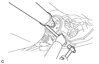
Pull out the propeller with center bearing shaft assembly from the transfer.
Note
-
When removing the propeller shaft, do not apply excessive force to the universal joint.
-
During and after the removal of the propeller shaft, keep the universal joint angle straight (within 15 degrees).
-
Be careful not to damage the oil seal.
-
-
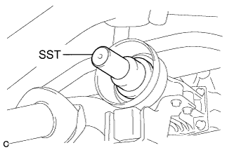
Insert SST into the transfer to prevent oil leaks.
- SST
- 09325-20010
Note
Be careful not to damage the oil seal.
-
-
SEPARATE REAR HEIGHT CONTROL SENSOR SUB-ASSEMBLY
-
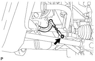
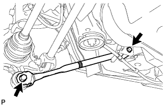
Remove the nut and separate the rear height control sensor sub-assembly from the rear No. 2 suspension arm assembly RH.
Note
Use wire or an equivalent tool to keep the rear height control sensor link from hanging down.
-
-
SEPARATE NO. 3 PARKING BRAKE CABLE ASSEMBLY
-
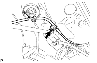
Remove the bolt and separate the No. 3 parking brake cable assembly.
-
-
SEPARATE NO. 2 PARKING BRAKE CABLE ASSEMBLY
Tech Tips
Perform the same procedure as the LH side.
-
REMOVE REAR STRUT ROD ASSEMBLY LH
-
Remove the 2 bolts, the 2 nuts and the rear strut rod assembly.
Note
Since stopper nuts are used, loosen the bolts.
-
-
REMOVE REAR STRUT ROD ASSEMBLY RH
Tech Tips
Perform the same procedure as the LH side.
-
REMOVE REAR NO. 2 SUSPENSION ARM ASSEMBLY LH
-
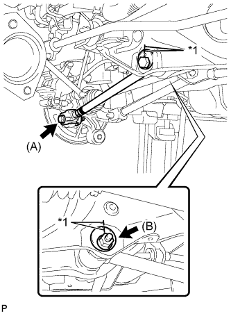
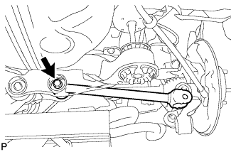
Text in Illustration *1 Matchmark Put matchmarks on the adjust cams and the rear suspension member sub-assembly.
-
Remove the bolt (A) and the nut, and separate the rear No. 2 suspension arm assembly LH from the rear axle carrier sub-assembly LH.
Note
Since a stopper nut is used, loosen the bolt.
-
Remove the nut (B), the No. 2 camber adjust cam, the rear suspension toe adjust cam sub-assembly, and the rear No. 2 suspension arm assembly LH.
Tech Tips
When removing the nut, keep the rear suspension toe adjust cam sub-assembly from rotating.
-
-
REMOVE REAR NO. 2 SUSPENSION ARM ASSEMBLY RH
Tech Tips
Perform the same procedure as the LH side.
-
SEPARATE REAR NO. 1 SUSPENSION ARM ASSEMBLY LH
-
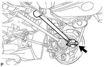
Remove the bolt and the nut, and separate the rear No. 1 suspension arm assembly LH from the rear axle carrier sub-assembly LH.
Note
Since a stopper nut is used, loosen the bolt.
-
-
SEPARATE REAR NO. 1 SUSPENSION ARM ASSEMBLY RH
Tech Tips
Perform the same procedure as the LH side.
-
REMOVE NO. 1 FLOOR UNDER COVER
-
Separate the 5 clips to remove the No. 1 floor under cover.
Tech Tips
Remove the No. 1 floor under cover with the 5 clips.
-
-
SEPARATE FRAME WIRE
-
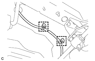
Disengage the 2 clamps to separate the frame wire from the body.
-
-
SEPARATE NO. 3 FLOOR WIRE
-
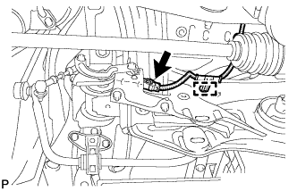
Disconnect the connector and disengage the clamp to separate the No. 3 floor wire from the rear suspension member.
-
-
SEPARATE REAR SUSPENSION MEMBER
-
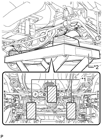
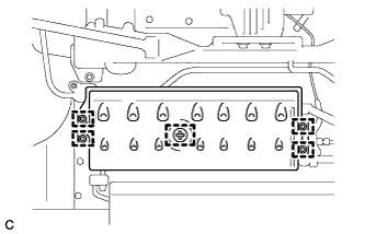
Text in Illustration *1 Wooden Block *2 Jack Support the rear suspension member with a jack using 3 wooden blocks as shown in the illustration.
Tech Tips
Use properly sized wooden blocks to keep the jack and suspension member level.
-
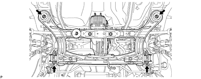
Remove the 4 nuts, 2 bolts and 2 rear lower suspension member stopper retainers.
-
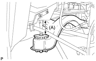
Lower the rear suspension member to the point shown in the illustration.
Length (A) 100 mm (3.94 in.)
-
-
REMOVE REAR NO. 1 SUSPENSION ARM ASSEMBLY LH
-
Remove the bolt, the nut and the rear No. 1 suspension arm assembly LH from the rear suspension member.
Note
Since a stopper nut is used, loosen the bolt.
-
-
REMOVE REAR NO. 1 SUSPENSION ARM ASSEMBLY RH
Tech Tips
Perform the same procedure as the LH side.