REAR LOWER ARM (for 2WD) INSTALLATION

-
TEMPORARILY INSTALL REAR NO. 1 SUSPENSION ARM ASSEMBLY LH
-
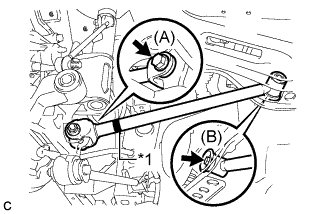
Text in Illustration *1 Identification Mark Temporarily install the rear No. 1 suspension arm assembly LH to the rear suspension member with the bolt (B).
Note
Ensure that the identification mark faces the rear side of the vehicle.
-
Temporarily install the rear No. 1 suspension arm assembly LH to the rear axle carrier sub-assembly with the bolt (A) and the nut.
Note
Since a stopper nut is used, temporarily tighten the bolt.
-
-
TEMPORARILY INSTALL REAR NO. 1 SUSPENSION ARM ASSEMBLY RH
Tech Tips
Perform the same procedure as the LH side.
-
TEMPORARILY INSTALL REAR NO. 2 SUSPENSION ARM ASSEMBLY LH
-
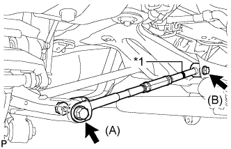
Text in Illustration *1 Identification Mark Temporarily install the rear No. 2 suspension arm assembly LH to the rear suspension member with the bolt (B).
Note
Ensure that the identification mark faces the rear side of the vehicle.
-
Temporarily install the rear No. 2 suspension arm assembly LH to the rear axle carrier sub-assembly LH with the bolt (A) and the nut.
Note
Since a stopper nut is used, temporarily tighten the bolt.
-
-
TEMPORARILY INSTALL REAR NO. 2 SUSPENSION ARM ASSEMBLY RH
-
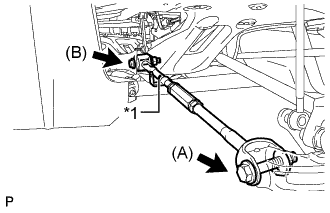
Text in Illustration *1 Identification Mark Temporarily install the rear No. 2 suspension arm assembly RH to the rear suspension member with the bolt (B).
Note
Ensure that the identification mark faces the rear side of the vehicle.
-
Temporarily install the rear No. 2 suspension arm assembly RH to the rear axle carrier sub-assembly RH with the bolt (B) and the nut.
Note
Since a stopper nut is used, temporarily tighten the bolt.
-
-
CONNECT REAR HEIGHT CONTROL SENSOR SUB-ASSEMBLY
-
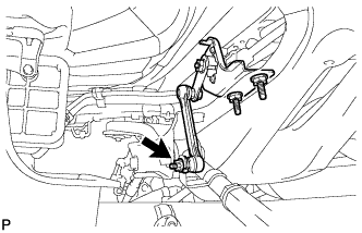
Connect the rear height control sensor sub-assembly to the rear No. 2 suspension arm assembly RH with the nut.
- Torque:
- 5.4 N*m { 55 kgf*cm, 48 in.*lbf }
-
-
STABILIZE SUSPENSION
-
Install the rear wheels.
- Torque:
- 103 N*m { 1050 kgf*cm, 76 ft.*lbf }
-
Lower the vehicle to the ground.
-
Bounce the vehicle up and down at the corners to stabilize the rear suspension.
-
Remove the rear wheels.
-
-
FULLY TIGHTEN REAR NO. 1 SUSPENSION ARM ASSEMBLY LH
-
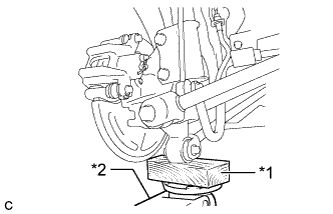
Text in Illustration *1 Wooden Block *2 Jack Support the rear axle carrier sub-assembly using a jack and wooden block as shown in the illustration.
Note
Do not bend the brake dust cover.
-
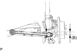
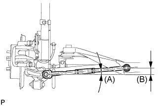
Jack up the rear axle carrier sub-assembly LH to set the rear No. 1 suspension arm assembly LH in the tightening position as shown in the illustration.
Standard angle (A) 4°36' (4.6°) Standard length (B) 38.6 mm (1.52 in.) CAUTION:
Do not jack up the rear axle carrier sub-assembly LH too high as the vehicle may fall.
Tech Tips
If the rear No. 1 suspension arm assembly LH cannot be positioned as shown in the illustration even when the rear axle carrier sub-assembly LH is jacked up, apply additional load to the vehicle such as by having a person sit in the rear seat.
-
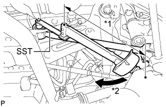
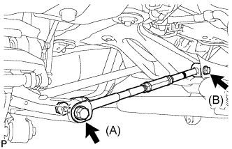
Using SST and a socket wrench (19 mm), fully tighten the bolt in the tightening position.
- SST
- 09961-00950
- Torque:
- without SST
- 120 N*m { 1224 kgf*cm, 89 ft.*lbf }
- with SST
- 89 N*m { 904 kgf*cm, 65 ft.*lbf }
Note
-
Use a torque wrench with a fulcrum length of 425 mm (1.39 ft.).
-
This torque value is effective when SST is parallel to the torque wrench.
-
Since a stopper nut is used, fully tighten the bolt.
-
Fully tighten the bolt in the tightening position.
- Torque:
- 112 N*m { 1142 kgf*cm, 83 ft.*lbf }
Note
Since a stopper nut is used, fully tighten the bolt.
-
-
FULLY TIGHTEN REAR NO. 1 SUSPENSION ARM ASSEMBLY RH
Tech Tips
Perform the same procedure as the LH side.
-
FULLY TIGHTEN REAR NO. 2 SUSPENSION ARM ASSEMBLY LH
-
Text in Illustration *1 Wooden Block *2 Jack Support the rear axle carrier sub-assembly using a jack and wooden block as shown in the illustration.
Note
Do not bend the brake dust cover.
-
Jack up the rear axle carrier sub-assembly LH to set the rear No. 2 suspension arm assembly LH in the tightening position as shown in the illustration.
Standard angle (A) 4°36' (4.6°) Standard length (B) 39.1 mm (1.54 in.) CAUTION:
Do not jack up the rear axle carrier sub-assembly LH too high as the vehicle may fall.
Tech Tips
If the rear No. 2 suspension arm assembly LH cannot be positioned as shown in the illustration even when the rear axle carrier sub-assembly LH is jacked up, apply additional load to the vehicle such as by having a person sit in the rear seat.
-
Fully tighten the bolts in the tightening position.
- Torque:
- Bolt (A)
- 112 N*m { 1142 kgf*cm, 83 ft.*lbf }
- Bolt (B)
- 120 N*m { 1224 kgf*cm, 89 ft.*lbf }
Note
Since a stopper nut is used, fully tighten the bolt (A) and (B).
-
-
FULLY TIGHTEN REAR NO. 2 SUSPENSION ARM ASSEMBLY RH
Tech Tips
Perform the same procedure as the LH side.
-
INSTALL REAR STABILIZER BAR
-
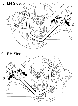
Install the rear stabilizer bar with the 4 bolts in order 1 to 2.
- Torque:
- 19 N*m { 194 kgf*cm, 14 ft.*lbf }
-
-
INSTALL REAR STABILIZER LINK ASSEMBLY LH
-

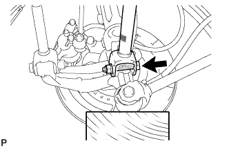
Text in Illustration *1 Turn *2 Hold Install the rear stabilizer link assembly LH to the rear stabilizer bar with the nut.
- Torque:
- 39 N*m { 400 kgf*cm, 29 ft.*lbf }
Tech Tips
If the ball joint turns together with the nut, use a hexagon wrench (5 mm) to hold the stud bolt.
-
-
INSTALL REAR STABILIZER LINK ASSEMBLY RH
Tech Tips
Perform the same procedure as the LH side.
-
INSTALL REAR WHEEL
- Torque:
- 103 N*m { 1050 kgf*cm, 76 ft.*lbf }
-
INSPECT AND ADJUST REAR WHEEL ALIGNMENT
-
Inspect and adjust the rear wheel alignment Click here.
-
-
HEIGHT CONTROL SENSOR SIGNAL INITIALIZATION
-
Initialize the height control sensor signal Click here.
-
-
INSPECT AND ADJUST HEADLIGHT AIMING
-
Inspect and adjust the headlight aiming Click here.
-