FRONT SUSPENSION MEMBER INSTALLATION

-
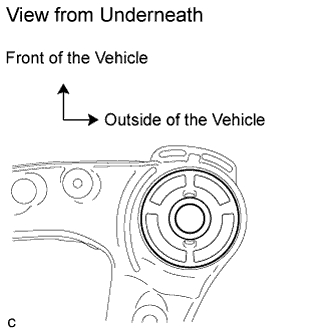
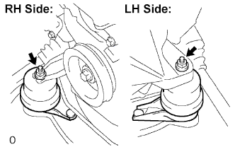
INSTALL FRONT SUSPENSION MEMBER BODY MOUNTING REAR CUSHION LH
-
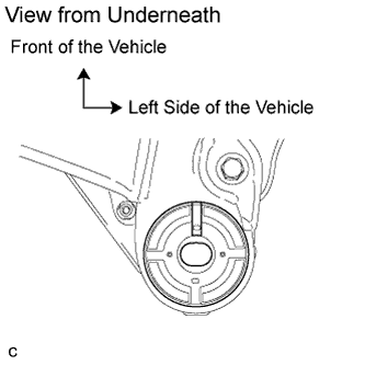
Temporarily install a new front suspension member body mounting rear cushion LH while confirming the installation direction.
Note
Position the front suspension member body mounting rear cushion in the correct direction.
-
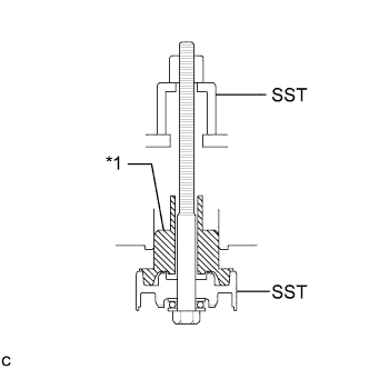
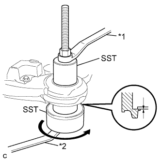
Text in Illustration *1 Front Suspension Member Body Mounting Rear Cushion Install SST as shown in the illustration.
- SST
- 09830-10010 ( 09830-01010, 09830-01020, 09830-01030, 09830-01060 )
-
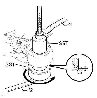
Text in Illustration *1 Hold *2 Turn Using SST, install the front suspension member body mounting rear cushion LH as shown in the illustration.
Note
Make sure that there is no clearance between the front suspension member and front suspension member body mounting rear cushion LH.
-
-
INSTALL FRONT SUSPENSION MEMBER BODY MOUNTING REAR CUSHION RH
-
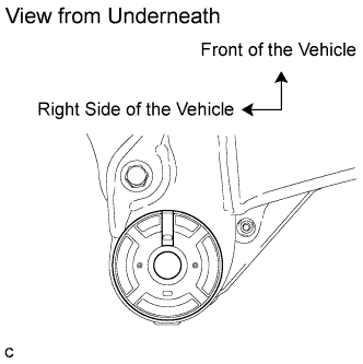
Temporarily install a new front suspension member body mounting rear cushion RH while confirming the installation direction.
Note
Position the front suspension member body mounting rear cushion in the correct direction.
-
Using SST, install the front suspension member body mounting rear cushion RH.
- SST
- 09830-10010 ( 09830-01010, 09830-01020, 09830-01030, 09830-01060 )
Tech Tips
Perform the same procedure as the LH side.
-
-
INSTALL FRONT SUSPENSION MEMBER BODY MOUNTING FRONT CUSHION
-
Temporarily install a new front suspension member body mounting front cushion while confirming the installation direction.
Note
Position the front suspension member body mounting front cushion in the correct direction.
-
Text in Illustration *1 Hold *2 Turn Using SST, install the front suspension member body mounting front cushion as shown in the illustration.
- SST
- 09830-10010 ( 09830-01010, 09830-01020, 09830-01030, 09830-01060 )
Note
Make sure that there is no clearance between the front suspension member and front suspension member body mounting rear cushion.
-
-
INSTALL FRONT SUSPENSION MEMBER BODY MOUNTING REAR STOPPER
-
INSTALL FRONT SUSPENSION MEMBER BODY MOUNTING FRONT STOPPER
-
INSTALL FRONT SUSPENSION MEMBER DYNAMIC DAMPER (for 2WD)
-
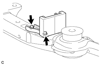
Install the front suspension member dynamic damper with the 2 bolts.
- Torque:
- 29 N*m { 296 kgf*cm, 21 ft.*lbf }
-
-
INSTALL FRONT LOWER SUSPENSION ARM LH
-
Install the front lower arm bushing stopper to the front lower suspension arm.
-
Temporarily tighten the front lower suspension arm to the front frame assembly with the 3 bolts and nut.
-
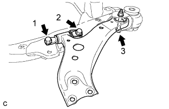
Tighten the 3 bolts in the order shown in the illustration.
- Torque:
- Bolt 1, 2
- 200 N*m { 2039 kgf*cm, 147 ft.*lbf }
- Bolt 3
- 135 N*m { 1377 kgf*cm, 100 ft.*lbf }
Tech Tips
Start installing the bolts from the front of the vehicle.
-
-
INSTALL FRONT LOWER SUSPENSION ARM RH
Tech Tips
Perform the same procedure as the LH side.
-
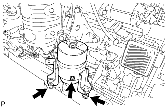
TEMPORARILY TIGHTEN FRONT ENGINE MOUNTING INSULATOR ASSEMBLY
-
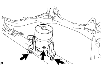
Temporarily install the front engine mounting insulator assembly with the 3 nuts.
Tech Tips
Perform this procedure only when replacement of the engine mounting insulator is necessary.
-
-
TEMPORARILY TIGHTEN ENGINE MOUNTING INSULATOR LH
-
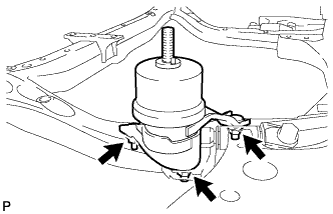
Temporarily install the engine mounting insulator LH with the 3 nuts.
Tech Tips
Perform this procedure only when replacement of the engine mounting insulator is necessary.
-
-
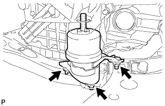
TEMPORARILY TIGHTEN ENGINE MOUNTING INSULATOR RH
-
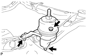
Temporarily install the engine mounting insulator RH with the 3 nuts.
Tech Tips
Perform this procedure only when replacement of the engine mounting insulator is necessary.
-
-
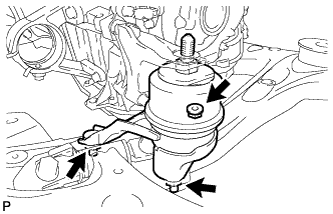
TEMPORARILY TIGHTEN REAR ENGINE MOUNTING INSULATOR ASSEMBLY (for AWD)
-
Temporarily install the rear engine mounting insulator with the 2 nuts.
Tech Tips
Perform this procedure only when replacement of the engine mounting insulator is necessary.
-
-
INSTALL FRONT FRAME ASSEMBLY
-
Set the engine assembly with transaxle to the front frame assembly.
-
Install the engine mounting insulators RH and LH with the 2 nuts.
- Torque:
- 95 N*m { 968 kgf*cm, 70 ft.*lbf }
-
Install the front engine mounting insulator with the bolt.
- Torque:
- 87 N*m { 887 kgf*cm, 64 ft.*lbf }
-
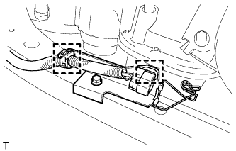
Connect the 2 clamps with the engine wire.
-
-
INSTALL REAR ENGINE MOUNTING INSULATOR ASSEMBLY (for AWD)
-
Install the rear engine mounting insulator assembly with the 2 bolts to the engine mounting bracket.
- Torque:
- 75 N*m { 764 kgf*cm, 55 ft.*lbf }
-
-
FULLY TIGHTEN FRONT ENGINE MOUNTING INSULATOR ASSEMBLY
-
Fully tighten the front engine mounting insulator with the 3 nuts.
- Torque:
- 52 N*m { 530 kgf*cm, 38 ft.*lbf }
-
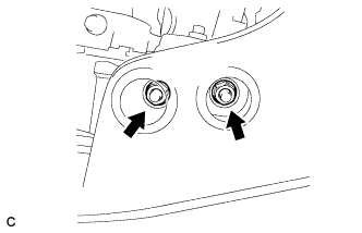
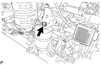
Install the hole plug.
Tech Tips
Perform this procedure only when replacement of the engine mounting insulator is necessary.
-
-
FULLY TIGHTEN ENGINE MOUNTING INSULATOR LH
-
Fully tighten the engine mounting insulator LH with the 3 nuts.
- Torque:
- 87 N*m { 887 kgf*cm, 64 ft.*lbf }
-
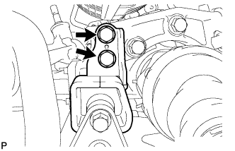
Install the 2 hole plugs.
Tech Tips
Perform this procedure only when replacement of the engine mounting insulator is necessary.
-
-
FULLY TIGHTEN ENGINE MOUNTING INSULATOR RH
-
Fully tighten the engine mounting insulator RH with the 3 nuts.
- Torque:
- 87 N*m { 887 kgf*cm, 64 ft.*lbf }
-
Install the 2 hole plugs.
Tech Tips
Perform this procedure only when replacement of the engine mounting insulator is necessary.
-
-
FULLY TIGHTEN REAR ENGINE MOUNTING INSULATOR ASSEMBLY (for AWD)
-
Fully tighten the rear engine mounting insulator with the 2 nuts.
- Torque:
- 52 N*m { 530 kgf*cm, 38 ft.*lbf }
-
Install the 2 hole plugs.
Tech Tips
Perform this procedure only when replacement of the engine mounting insulator is necessary.
-
-
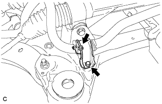
INSTALL STEERING LINK ASSEMBLY
-
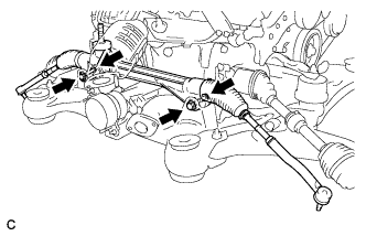
Install the steering link assembly with the 2 bolts and 2 nuts.
- Torque:
- 70 N*m { 713 kgf*cm, 51 ft.*lbf }
Note
-
Make sure to tighten the bolts starting from the left side of the vehicle.
-
Because the nut has its own stopper, do not turn the nut. Tighten the bolt with the nut secured.
-
-
INSTALL FRONT STABILIZER BAR WITH FRONT STABILIZER LINK ASSEMBLY
-
INSTALL FRONT NO. 1 STABILIZER BRACKET LH
-
Install the front No. 1 stabilizer bracket LH to the front frame assembly with the 2 bolts.
- Torque:
- 29 N*m { 296 kgf*cm, 21 ft.*lbf }
-
-
INSTALL FRONT NO. 1 STABILIZER BRACKET RH
Tech Tips
Perform the same procedure as the LH side.
-
INSTALL ENGINE ASSEMBLY WITH TRANSAXLE
Tech Tips
Refer to the procedure from Install Engine Assembly with Transaxle Click here.