REAR DIFFERENTIAL CARRIER ASSEMBLY DISASSEMBLY

-
SECURE DIFFERENTIAL CARRIER ASSEMBLY
-
Secure the differential carrier assembly to the overhaul stand, etc.
-
-
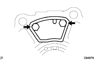
REMOVE REAR DIFFERENTIAL FILLER PLUG
-
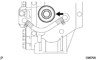
Using a hexagon wrench (17 mm), remove the rear differential filler plug (inspection plug) and gasket.
-
-
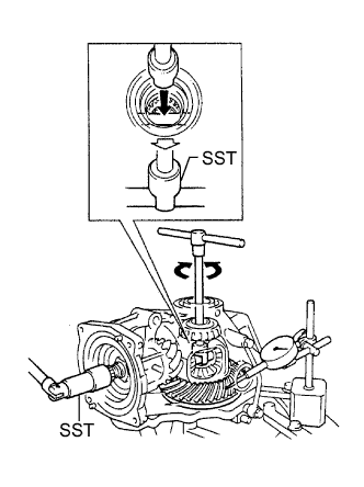
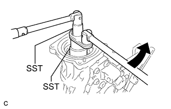
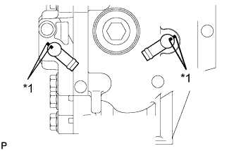
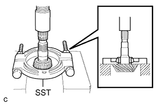
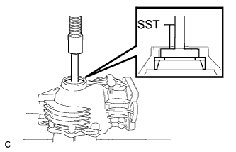
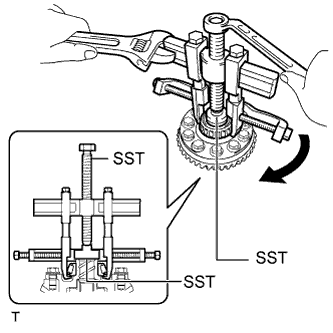
REMOVE STUD BOLT
-
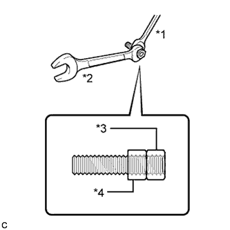
Text in Illustration *1 Hold *2 Turn *3 Upper Nut *4 Lower Nut Install 2 service nuts to the stud bolt.
Recommended service nut Thread diameter 8 mm (0.3150 in.) Thread pitch 1.25 mm (0.0492 in.) -
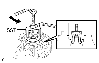
Lock the upper nut using the lower nut.
-
Turn the lower nut and remove the other 3 stud bolts in the same way.
Tech Tips
If the threads of the electro magnetic control coupling sub-assembly are damaged while removing the stud bolt, replace the electro magnetic control coupling sub-assembly with a new one.
-
-
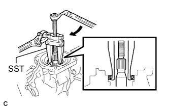
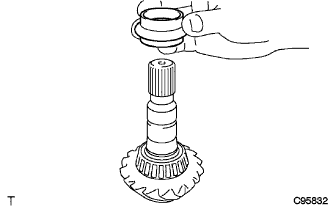
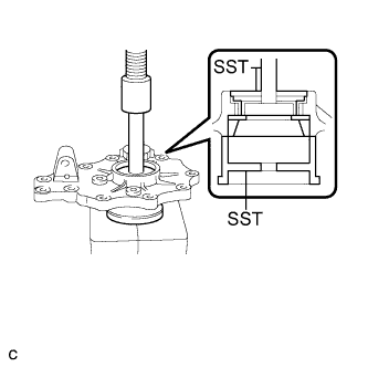
INSPECT RUNOUT OF ELECTRO MAGNETIC CONTROL COUPLING SUB-ASSEMBLY
-
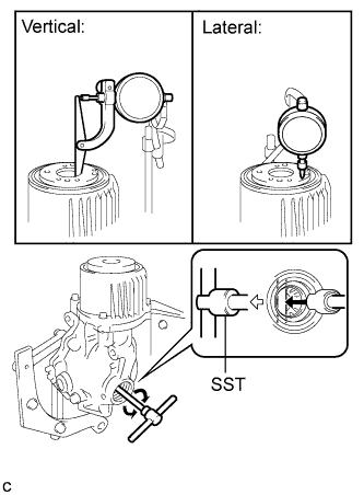
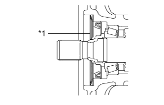
Install a dial indicator and magnetic base perpendicular to the inner side of the electro magnetic control coupling sub-assembly as shown in the illustration.
-
Using SST, rotate the electro magnetic control coupling sub-assembly forward and backward, and measure the vertical runout.
- SST
- 09564-32011
Maximum runout 0.065 mm (0.00255 in.) If the runout is greater than the maximum value, replace the electro magnetic control coupling sub-assembly.
-
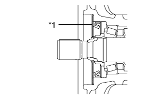
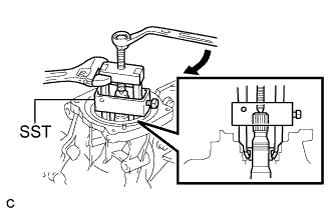
Install a dial indicator and magnetic base perpendicular to the electro magnetic control coupling sub-assembly as shown in the illustration.
-
Using SST, rotate the electro magnetic control coupling sub-assembly forward and backward, and measure the lateral runout.
- SST
- 09564-32011
Maximum runout 0.073 mm (0.00287 in.) If the runout is greater than the maximum value, replace the electro magnetic control coupling sub-assembly.
-
-
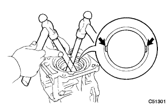
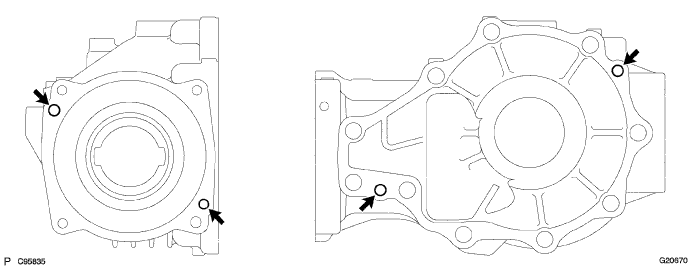
REMOVE ELECTRO MAGNETIC CONTROL COUPLING SUB-ASSEMBLY
-
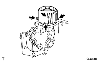
Remove the 4 bolts. Using a plastic hammer, lightly tap the electro magnetic control coupling sub-assembly to remove it from the rear differential carrier assembly.
-
-
REMOVE TRANSMISSION COUPLING CONICAL SPRING WASHER
-
Text in Illustration *1 Transmission Coupling Conical Spring Washer Remove the transmission coupling conical spring washer from the rear differential carrier assembly.
-
-
REMOVE TRANSMISSION COUPLING SPACER
-
Text in Illustration *1 Transmission Coupling Spacer Remove the transmission coupling spacer from the rear differential carrier assembly.
-
-
REMOVE REAR DIFFERENTIAL DUST DEFLECTOR
-
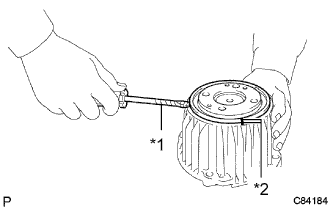
Text in Illustration *1 Tape *2 Matchmark Put matchmarks on the rear differential dust deflector and electro magnetic control coupling sub-assembly.
-
Using a screwdriver, remove the rear differential dust deflector.
Note
-
Pry the circumference of the rear differential dust deflector uniformly to prevent deformation.
-
Do not damage the end surface of the electro magnetic control coupling sub-assembly.
Tech Tips
-
Tape the screwdriver tip before use.
-
If the end surface of the electro magnetic control coupling sub-assembly are damaged while removing the rear differential dust deflector, replace the electro magnetic control coupling sub-assembly with a new one.
-
-
-
REMOVE CONNECTOR CLAMP BRACKET
-
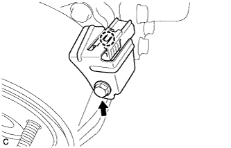
Disengage the claw and separate the connector.
-
Remove the bolt and connector clamp bracket.
Note
Do not damage the electro magnetic control coupling wire harness.
-
-
INSPECT DIFFERENTIAL RING GEAR BACKLASH
-
Insert a dial indicator and magnetic base through the rear differential filler plug hole, and set it perpendicular to a ring gear tooth tip.
-
Using SST, hold the drive pinion in place.
- SST
- 09556-16011
-
Using SST, rotate the rear differential case forward and backward, and measure the backlash.
- SST
- 09564-32011
Backlash 0.10 to 0.22 mm (0.00394 to 0.00866 in.) Note
Measure at 3 or more areas on the circumference of the ring gear.
If the backlash is not within the specification, adjust the side bearing preload or repair as necessary.
-
-
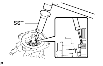
INSPECT DIFFERENTIAL DRIVE PINION PRELOAD
-
Using SST and a torque wrench, inspect the differential drive pinion preload (starting torque) of the backlash between the differential drive pinion and differential ring gear.
- SST
- 09556-16011
Standard drive pinion preload 0.4 to 0.7 N*m (4 to 7 kgf*cm, 3 to 6 in.*lbf) Note
For a more accurate measurement, rotate the rear differential case bearing forward and backward before measuring.
If the preload is not within the specified range, adjust the total preload or repair as necessary.
-
-
INSPECT TOTAL PRELOAD
-
Using SST and a torque wrench, inspect the total preload (starting torque) with the teeth of the differential drive pinion and differential ring gear in contact.
- SST
- 09556-16011
Standard total preload Standard drive pinion preload plus 0.3 to 0.5 N*m (3 to 4 kgf*cm, 3 to 4 in.*lbf) Note
For a more accurate measurement, rotate the rear differential case bearing forward and backward before measuring.
If the preload is not within the specified range, adjust the total preload or repair as necessary.
-
-
REMOVE REAR DIFFERENTIAL SIDE GEAR SHAFT OIL SEAL
-
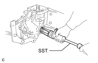
Using SST, remove the 2 rear differential side gear shaft oil seals from the rear differential carrier assembly.
- SST
- 09308-00010
-
-
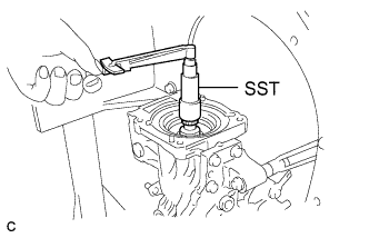
REMOVE REAR DRIVE PINION NUT
-
Using SST and a hammer, unstake the rear drive pinion nut.
- SST
- 09930-00010
Note
-
Use SST with the tapered part facing against the shaft.
-
Do not modify the SST tip with a grinder or equivalent.
-
Fully unstake the rear drive pinion nut.
-
Using SST, hold the differential drive pinion in place and remove the rear drive pinion nut from the differential drive pinion.
- SST
- 09556-16011
- 09564-16020
-
-
REMOVE DIAPHRAGM OIL SEAL
-
Using SST, remove the diaphragm oil seal from the rear differential carrier assembly.
- SST
- 09308-10010
-
-
REMOVE REAR DRIVE PINION FRONT TAPERED ROLLER BEARING
-
Using SST, remove the rear drive pinion front tapered roller bearing (inner race) from the differential drive pinion.
- SST
- 09556-40010
-
-
REMOVE DIFFERENTIAL PRESSURE CONTROL HOSE
-
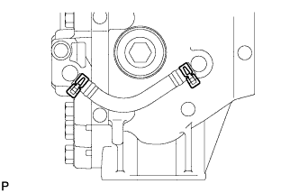
Remove the 2 differential pressure control hose clips and rear differential pressure control hose.
-
-
REMOVE DIFFERENTIAL PRESSURE CONTROL HOSE ELBOW
-
Text in Illustration *1 Matchmark Put matchmarks on the 2 differential pressure control hose elbows and rear differential carrier assembly.
-
Using a screwdriver, remove the 2 differential pressure control hose elbows.
Tech Tips
Tape the screwdriver tip before use.
-
-
REMOVE DIFFERENTIAL SIDE BEARING RETAINER
-
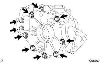
Remove the 10 bolts from the rear differential carrier assembly.
-
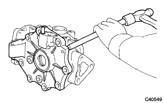
Using a brass bar and a hammer, lightly tap out the differential side bearing retainer from the rear differential carrier assembly.
Note
Set the brass bar on the ribbed part of the differential side bearing retainer.
-
-
REMOVE REAR DIFFERENTIAL CARRIER COVER BREATHER PLUG
-
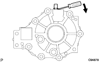
Using a screwdriver, remove the rear differential carrier cover breather plug from the differential side bearing retainer.
Tech Tips
Tape the screwdriver tip before use.
-
-
REMOVE REAR DIFFERENTIAL BREATHER PLUG OIL DEFLECTOR
-
Remove the 2 bolts and rear differential breather plug oil deflector.
-
-
REMOVE REAR DIFFERENTIAL CASE SUB-ASSEMBLY
-
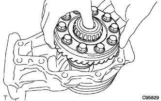
Remove the rear differential case sub-assembly from the rear differential carrier.
-
-
REMOVE DIFFERENTIAL DRIVE PINION
-
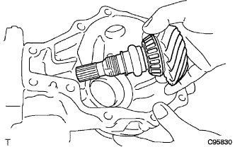
Remove the differential drive pinion from the rear differential carrier.
-
-
REMOVE REAR DIFFERENTIAL DRIVE PINION OIL SLINGER
-
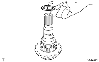
Remove the rear differential drive pinion oil slinger from the differential drive pinion.
-
-
REMOVE REAR DIFFERENTIAL DRIVE PINION BEARING SPACER
-
Remove the rear differential drive pinion bearing spacer from the differential drive pinion.
-
-
REMOVE REAR DRIVE PINION REAR TAPERED ROLLER BEARING
-
Using SST and a press, press out the rear drive pinion rear tapered roller bearing (inner race) from the differential drive pinion.
- SST
- 09950-00020
Note
If the rear differential drive pinion or differential ring gear is damaged, replace them both.
-
Remove the rear differential drive pinion plate washer.
-
-
REMOVE REAR DRIVE PINION FRONT TAPERED ROLLER BEARING
-
Using SST, remove the rear drive pinion front tapered roller bearing (outer race) from the rear differential carrier.
- SST
- 09612-65014 ( 09612-01020, 09612-01050 )
-
-
REMOVE REAR DRIVE PINION REAR TAPERED ROLLER BEARING
-
Using a brass bar and a hammer, lightly and uniformly tap out the rear drive pinion rear tapered roller bearing (outer race) from the rear differential carrier.
Note
Set the brass bar on the notch.
-
-
REMOVE REAR DIFFERENTIAL CASE BEARING
-
Using SST and a press, remove the rear differential case bearing (RH side outer race) and rear differential side gear shaft plate washer from the rear differential carrier.
- SST
- 09950-60010 ( 09951-00580 )
- 09950-70010 ( 09951-07100 )
-
-
REMOVE REAR DIFFERENTIAL CASE BEARING
-
Using SST and a press, remove the rear differential case bearing (LH side outer race) and rear differential side gear shaft plate washer from the differential side bearing retainer.
- SST
- 09950-60010 ( 09951-00580 )
- 09950-70010 ( 09951-07100 )
- 09223-15020
-
-
REMOVE STRAIGHT PIN
-
Remove the 4 straight pins from the rear differential carrier.
-
-
REMOVE REAR DIFFERENTIAL CASE BEARING
-
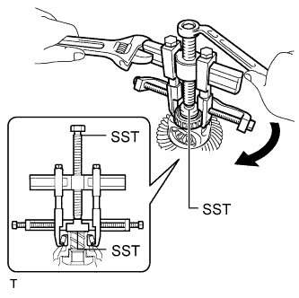
Using SST, remove the rear differential case bearing (RH side inner race) from the rear differential case sub-assembly.
- SST
- 09950-40011 ( 09951-04020, 09952-04010, 09953-04020, 09954-04010, 09955-04011, 09957-04010, 09958-04011 )
- 09950-60010 ( 09951-00370 )
Note
Before using the SST center bolt (09953-04020), apply hypoid gear oil to its threads and tip.
Tech Tips
If the race remains on the rear differential case sub-assembly, repeat the step above to remove the race.
-
-
REMOVE REAR DIFFERENTIAL CASE BEARING
-
Using SST, remove the rear differential case bearing (LH side inner race) from the rear differential case.
- SST
- 09950-40011 ( 09951-04020, 09952-04010, 09953-04020, 09954-04010, 09955-04061, 09957-04010, 09958-04011 )
- 09950-60010 ( 09951-00370 )
Note
Before using the SST center bolt (09953-04020), apply hypoid gear oil to its threads and tip.
Tech Tips
If the race remains on the rear differential case sub-assembly, repeat the step above to remove the race.
-
-
REMOVE DIFFERENTIAL RING GEAR
-
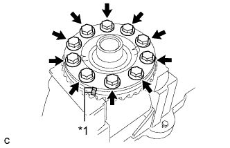
Text in Illustration *1 Matchmark Place matchmarks on the rear differential case and differential ring gear.
-
Remove the 10 ring gear set bolts.
-
Using a plastic-faced hammer, lightly tap the outer circumference of the differential ring gear to remove it from the rear differential case sub-assembly.
-
-
REMOVE REAR DIFFERENTIAL CASE SUB-ASSEMBLY
-
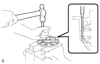
Using a pin punch (3 mm) and a hammer, remove the rear differential pinion shaft pin.
-
-
REMOVE DIFFERENTIAL PINION AND SIDE GEAR
-
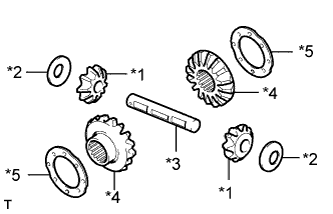
Text in Illustration *1 Differential Pinion Gear *2 Rear Differential Pinion Thrust Washer *3 Rear Differential Pinion Shaft *4 Differential Side Gear *5 Rear No. 1 Differential Side Gear Thrust Washer Remove the following components from the rear differential case:
-
-
INSPECT DIFFERENTIAL PINION AND SIDE GEAR
-
Check the differential pinion gears and differential side gears for wear.
-
-
INSPECT REAR DIFFERENTIAL CASE SUB-ASSEMBLY
-
Check the differential case for cracks or damage.
-