REAR DIFFERENTIAL SIDE GEAR SHAFT OIL SEAL REPLACEMENT

Tech Tips
-
Use the same procedure for the RH side and LH side.
-
The procedure listed below is for the LH side.
-
DRAIN DIFFERENTIAL OIL
-
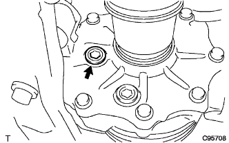
Using a hexagon wrench (10 mm), remove the rear differential carrier cover plug and gasket.
-
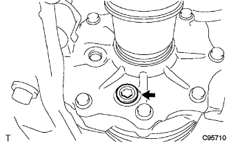
Using a hexagon wrench (10 mm), remove the rear differential drain plug and gasket, then drain the differential oil.
-
Using a hexagon wrench (10 mm), install the rear differential drain plug with a new gasket.
- Torque:
- 39 N*m { 398 kgf*cm, 29 ft.*lbf }
-
Using a hexagon wrench (10 mm), temporarily install the rear differential carrier cover plug.
Tech Tips
Add differential oil before installing a new gasket and fully tightening the rear differential carrier cover plug.
-
-
REMOVE REAR WHEEL
-
REMOVE CENTER EXHAUST PIPE ASSEMBLY (for RH Side)
-
Remove the center exhaust pipe assembly.
Tech Tips
Refer to the instructions for Removal of the exhaust pipe Click here.
-
-
SEPARATE REAR SPEED SENSOR
-
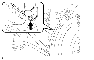
Remove the bolt and separate the rear speed sensor LH from the rear axle carrier sub-assembly.
Note
Keep the sensor tip and rear speed sensor installation hole free from foreign matter.
-
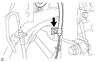
Remove the bolt and separate the rear speed sensor LH from the rear shock absorber with coil spring.
-
-
REMOVE REAR AXLE SHAFT NUT
-
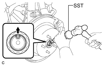
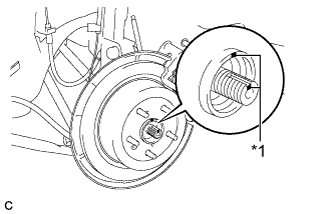
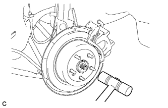
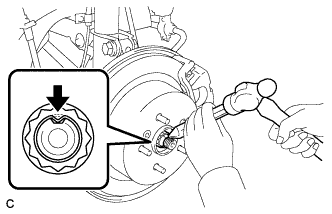
Using SST and a hammer, release the staked part of the rear axle shaft nut.
- SST
- 09930-00010
Note
Loosen the staked part of the nut completely, otherwise the threads of the drive shaft may be damaged.
-
While applying the brakes, remove the rear axle shaft nut.
-
-
SEPARATE NO. 3 PARKING BRAKE CABLE ASSEMBLY
-
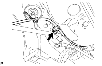
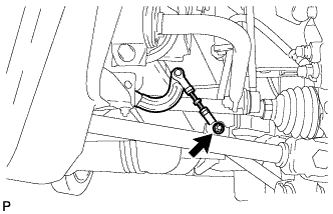
Remove the bolt and separate the No. 3 parking brake cable assembly.
-
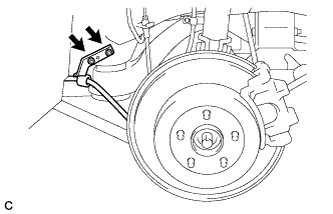
Remove the 2 nuts and separate the No. 3 parking brake cable assembly.
-
-
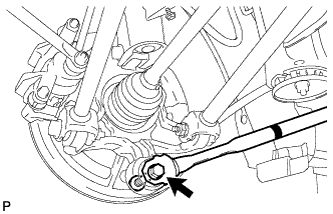
REMOVE REAR STRUT ROD ASSEMBLY
-
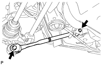
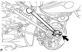
Remove the 2 bolts, the 2 nuts and the rear strut rod assembly.
Note
Since stopper nuts are used, loosen the bolts.
-
-
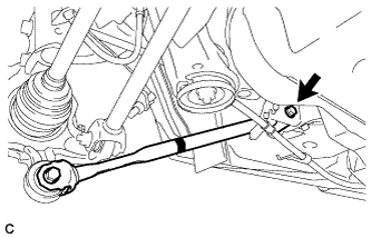
SEPARATE REAR HEIGHT CONTROL SENSOR SUB-ASSEMBLY
-
Remove the nut and separate the rear height control sensor sub-assembly from the rear No. 2 suspension arm assembly RH.
Note
Use wire or an equivalent tool to keep the rear height control sensor link from hanging down.
-
-
REMOVE REAR NO. 2 SUSPENSION ARM ASSEMBLY
-

Text in Illustration *1 Matchmark Put matchmarks on the adjust cams and the rear suspension member sub-assembly.
-
Remove the bolt (A) and the nut, and separate the rear No. 2 suspension arm assembly LH from the rear axle carrier sub-assembly LH.
Note
Since a stopper nut is used, loosen the bolt.
-
Remove the nut (B), the No. 2 camber adjust cam, the rear suspension toe adjust cam sub-assembly, and the rear No. 2 suspension arm assembly LH.
Tech Tips
When removing the nut, keep the rear suspension toe adjust cam sub-assembly from rotating.
-
-
SEPARATE REAR NO. 1 SUSPENSION ARM ASSEMBLY
-
Remove the bolt and the nut, and separate the rear No. 1 suspension arm assembly LH from the rear axle carrier sub-assembly LH.
Note
Since a stopper nut is used, loosen the bolt.
-
-
REMOVE REAR DRIVE SHAFT ASSEMBLY
-
Text in Illustration *1 Matchmark Put matchmarks on the rear drive shaft assembly and rear axle hub.
-
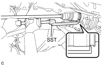
Using SST, disengage the rear drive shaft assembly from the rear differential carrier assembly.
- SST
- 09520-01010
- 09520-24010 ( 09520-32040 )
Note
Remove the rear drive shaft assembly while keeping it level.
-
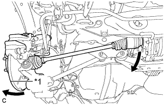
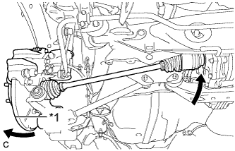
Text in Illustration *1 Rear Axle Assembly Separate the rear drive shaft assembly from the rear differential carrier assembly while pushing the rear axle assembly towards the outside of the vehicle.
Note
Do not disjoint inboard of the drive shaft.
-
Using a plastic hammer, remove the rear drive shaft assembly from the rear axle assembly.
Note
Do not drop the rear drive shaft assembly.
-
-
REMOVE REAR DRIVE SHAFT SNAP RING
-
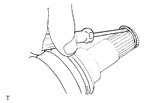
Using a screwdriver, remove the rear drive shaft snap ring.
-
-
REMOVE REAR DIFFERENTIAL SIDE GEAR SHAFT OIL SEAL
-
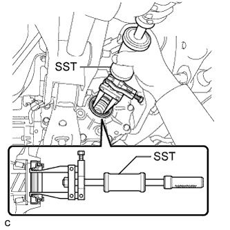
Using SST, remove the rear differential side gear shaft oil seal from the differential carrier assembly.
- SST
- 09308-00010
-
-
INSTALL REAR DIFFERENTIAL SIDE GEAR SHAFT OIL SEAL
-
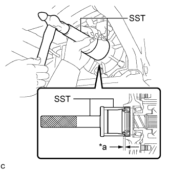
Text in Illustration *a Oil Seal Drive in Depth Using SST and a hammer, tap a new rear differential side gear shaft oil seal into the differential carrier assembly.
- SST
- 09517-30010
- 09631-32020
Oil seal drive in depth 6.8 to 7.8 mm (0.268 to 0.307 in.) -
Apply a light coat of MP grease to the lip of the new rear differential side gear shaft oil seal.
-
-
INSTALL REAR DRIVE SHAFT SNAP RING
-
Install a new rear drive shaft snap ring.
-
-
INSTALL REAR DRIVE SHAFT ASSEMBLY
-
Text in Illustration *1 Matchmark Align the matchmarks and insert the rear drive shaft assembly to the rear axle assembly.
-
Text in Illustration *1 Rear Axle Assembly Insert the rear drive shaft assembly to the rear differential carrier assembly while pushing the rear axle assembly towards the outside of the vehicle.
Note
Do not disjoint inboard of the drive shaft.
-
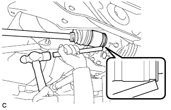
Using a brass bar and a hammer, engage the rear drive shaft assembly to the rear differential carrier assembly.
Note
-
Set the rear drive shaft snap ring with the opening facing downward.
-
Be careful not to damage the rear differential side gear shaft oil seal, rear drive shaft inboard joint boot and rear drive shaft dust cover.
-
Install the rear drive shaft assembly while keeping it level.
-
-
-
CONNECT REAR NO. 1 SUSPENSION ARM ASSEMBLY
-
Connect the rear No. 1 suspension arm assembly LH to the rear axle carrier sub-assembly LH with the bolt and the nut.
- Torque:
- 112 N*m { 1142 kgf*cm, 83 ft.*lbf }
Note
Since a stopper nut is used, temporarily tighten the bolt.
-
-
INSTALL REAR NO. 2 SUSPENSION ARM ASSEMBLY
-
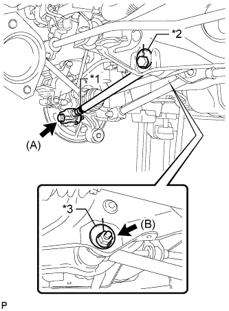
Text in Illustration *1 Identification Mark *2 Rear Suspension Toe Adjust Cam Sub-assembly *3 No. 2 Camber Adjust Cam Temporarily tighten the rear No. 2 suspension arm assembly LH to the rear suspension member with the rear suspension toe adjust cam sub-assembly, the No. 2 camber adjust cam and the nut (B).
Note
Ensure that the identification mark faces the rear side of the vehicle.
Tech Tips
When temporarily tightening the nut, keep the rear suspension toe adjust cam sub-assembly from rotating.
-
Fully tighten the rear No. 2 suspension arm assembly LH to the rear axle carrier sub-assembly LH with the bolt (A) and the nut.
- Torque:
- 112 N*m { 1142 kgf*cm, 83 ft.*lbf }
Note
Since a stopper nut is used, fully tighten the bolt.
-
-
INSTALL REAR HEIGHT CONTROL SENSOR SUB-ASSEMBLY
-
Connect the rear height control sensor sub-assembly to the rear No. 2 suspension arm assembly RH with the nut.
- Torque:
- 5.4 N*m { 55 kgf*cm, 48 in.*lbf }
-
-
INSTALL REAR STRUT ROD ASSEMBLY
-

Text in Illustration *1 Identification Mark Temporarily install the rear strut rod assembly to the rear axle carrier sub-assembly with the bolt and the nut.
Note
-
Ensure that the identification mark faces the inside of the vehicle.
-
Since a stopper nut is used, temporarily tighten the bolt.
-
-
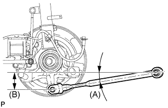
Set the rear strut rod assembly in the tightening position shown in the illustration.
Standard angle (A) 9°3' (9.04°) Standard length (B) 78.3 mm (3.08 in.) -
Fully tighten the bolt in the tightening position.
- Torque:
- 80 N*m { 816 kgf*cm, 59 ft.*lbf }
-
Temporarily install the rear strut rod assembly to the body with the bolt and the nut.
-
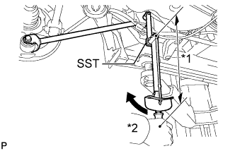
Text in Illustration *1 Fulcrum Length *2 Turn Using SST and a socket wrench (17 mm), fully tighten the bolt in the rebound position.
- SST
- 09961-00950
- Torque:
- without SST
- 80 N*m { 816 kgf*cm, 59 ft.*lbf }
- with SST
- 59 N*m { 603 kgf*cm, 44 ft.*lbf }
Note
-
Since a stopper nut is used, fully tighten the bolt.
-
Use a torque wrench with a fulcrum length of 425 mm (1.39 ft.).
-
This torque value is effective when SST is parallel to the torque wrench.
-
-
CONNECT NO. 3 PARKING BRAKE CABLE ASSEMBLY
-
Install the No. 3 parking brake cable assembly with the bolt.
- Torque:
- 6.0 N*m { 61 kgf*cm, 53 in.*lbf }
-
Install the No. 3 parking brake cable assembly with the 2 nuts.
- Torque:
- 6.0 N*m { 61 kgf*cm, 53 in.*lbf }
-
-
INSTALL REAR AXLE SHAFT NUT
-
Clean the threaded parts on the drive shaft and axle shaft nut using a non-residue solvent.
Note
-
Be sure to perform this work for a new drive shaft.
-
Keep the threaded parts free of oil and foreign objects.
-
-
Install a new rear axle shaft nut.
- Torque:
- 294 N*m { 2998 kgf*cm, 217 ft.*lbf }
-
Using a chisel and hammer, stake the rear axle shaft nut.
-
-
CONNECT REAR SPEED SENSOR
-
Install the rear speed sensor LH to the rear shock absorber with coil spring with the bolt.
- Torque:
- 8.0 N*m { 82 kgf*cm, 71 in.*lbf }
Note
Do not twist the rear speed sensor wire when installing it.
-
Install the rear speed sensor LH to the rear axle carrier sub-assembly with the bolt.
- Torque:
- 8.5 N*m { 87 kgf*cm, 75 in.*lbf }
Note
-
Keep the rear speed sensor tip and sensor installation hole free from foreign matter.
-
Do not twist the rear speed sensor wire when installing it.
-
-
INSTALL CENTER EXHAUST PIPE ASSEMBLY (for RH Side)
-
Install the center exhaust pipe assembly.
Tech Tips
Refer to the instructions for Installation of the exhaust pipe Click here.
-
-
ADD DIFFERENTIAL OIL
-
Remove the rear differential carrier cover plug.
-
Add differential oil Click here.
-
-
INSPECT AND ADJUST DIFFERENTIAL OIL
-
Stop the vehicle in a level place.
-
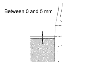
Check that the oil level is between 0 and 5 mm (0 and 0.197 in.) from the bottom lip of the rear differential carrier cover plug opening.
Note
-
When adding differential oil, make sure that the vehicle is level.
-
An excessively large or small amount of differential oil may cause damage.
-
After adding differential oil, drive the vehicle and recheck the oil level.
-
-
Inspect for oil leak if the oil level is low.
-
-
INSTALL REAR DIFFERENTIAL CARRIER COVER PLUG
-
Using a hexagon wrench (10 mm), install the rear differential carrier cover plug and a new gasket.
- Torque:
- 39 N*m { 398 kgf*cm, 29 ft.*lbf }
-
-
INSPECT FOR DIFFERENTIAL OIL LEAK
-
INSTALL REAR WHEEL
- Torque:
- 105 N*m { 1050 kgf*cm, 76 ft.*lbf }
-
STABILIZE SUSPENSION
-
Lower the vehicle to the ground.
-
Bounce the vehicle up and down at the corners to stabilize the rear suspension.
-
-
FULLY TIGHTEN REAR NO. 2 SUSPENSION ARM ASSEMBLY
-
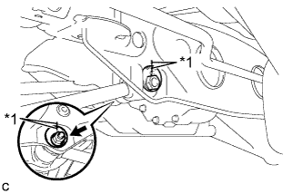
Text in Illustration *1 Matchmark Align the matchmarks on the adjust cams and rear suspension member sub-assembly.
-
Fully tighten the nut.
- Torque:
- 100 N*m { 1020 kgf*cm, 74 ft.*lbf }
Note
The final torque must be applied under standard vehicle height conditions.
Tech Tips
When fully tightening the nut, keep the rear suspension toe adjust cam sub-assembly from rotating.
-
-
INSPECT AND ADJUST REAR WHEEL ALIGNMENT
-
Inspect and adjust the rear wheel alignment Click here.
-
-
CHECK FOR SPEED SENSOR SIGNAL
-
Check for the speed sensor signal Click here.
-
-
HEIGHT CONTROL SENSOR SIGNAL INITIALIZATION
-
Initialize the height control sensor signal Click here.
-
-
INSPECT AND ADJUST HEADLIGHT AIMING
-
Inspect and adjust the headlight aiming Click here.
-