REAR DIFFERENTIAL CARRIER OIL SEAL REPLACEMENT

-
REMOVE CENTER EXHAUST PIPE ASSEMBLY
-
Remove the center exhaust pipe assembly Click here.
-
-
REMOVE PROPELLER WITH CENTER BEARING SHAFT ASSEMBLY
-
Depress the brake pedal and hold it.
-
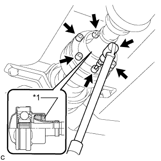
Text in Illustration *1 Piece of Cloth Using a hexagon wrench (6 mm), loosen the cross groove joint set bolts 1/2 turn.
Note
-
Put a piece of cloth or equivalent into the inside of the universal joint cover so that the boot does not touch the inside of the universal joint cover.
-
Do not remove the bolts.
-
-
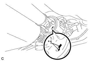
Text in Illustration *1 Matchmark Place matchmarks on the rear propeller shaft and electromagnetic control coupling assembly.
-
Remove the 4 nuts and 4 washers.
-
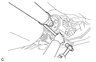
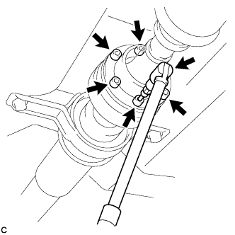
Using a brass bar and a hammer, separate the propeller with center bearing shaft assembly.
-
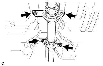
Remove the 4 bolts, 2 No. 1 center support bearing washers and 2 No. 2 center support bearing washers.
Note
When removing the bolts and washers, do not apply excessive force to the universal joint.
-
Pull out the propeller with center bearing shaft assembly from the transfer.
Note
-
When removing the propeller shaft, do not apply excessive force to the universal joint.
-
During and after the removal of the propeller shaft, keep the universal joint angle straight (within 15 degrees).
-
Be careful not to damage the oil seal.
-
-
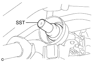
Insert SST into the transfer to prevent oil leaks.
- SST
- 09325-20010
Note
Be careful not to damage the oil seal.
-
-
DRAIN DIFFERENTIAL OIL
-
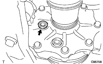
Using a 10 mm hexagon wrench, remove the rear differential carrier cover plug and gasket.
-
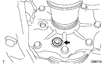
Using a 10 mm hexagon wrench, remove the rear differential drain plug and gasket to drain the differential oil.
-
Using a 10 mm hexagon wrench, install a new gasket and the rear differential drain plug.
- Torque:
- 39 N*m { 398 kgf*cm, 29 ft.*lbf }
-
Using a 10 mm hexagon wrench, temporarily install the rear differential carrier cover plug.
Tech Tips
Add differential oil before installing a new gasket and fully tightening the rear differential carrier cover plug.
-
-
REMOVE ELECTRO MAGNETIC CONTROL COUPLING SUB-ASSEMBLY
-
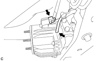
Disconnect the electro magnetic control coupling sub-assembly connector and vacuum hose.
Note
Do not damage the electro magnetic control coupling wire harness.
-
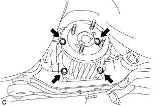
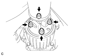
Remove the 4 bolts.
-
Using a brass bar and a hammer, tap the electro magnetic control coupling sub-assembly to remove the electro magnetic control coupling sub-assembly from the rear differential carrier assembly.
Note
Do not drop the electro magnetic control coupling sub-assembly.
-
-
REMOVE TRANSMISSION COUPLING CONICAL SPRING WASHER
-
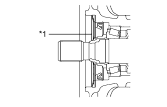
Text in Illustration *1 Transmission Coupling Conical Spring Washer Remove the transmission coupling conical spring washer from the rear differential carrier assembly.
-
-
REMOVE TRANSMISSION COUPLING SPACER
-
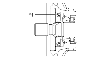
Text in Illustration *1 Transmission Coupling Spacer Remove the transmission coupling spacer from the rear differential carrier assembly.
-
-
REMOVE DIAPHRAGM OIL SEAL
-
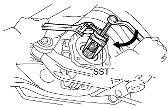
Using SST, remove the diaphragm oil seal from the rear differential carrier assembly.
- SST
- 09308-10010
-
-
INSTALL DIAPHRAGM OIL SEAL
-
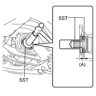
Using SST and a hammer, install a new diaphragm oil seal into the rear differential carrier assembly.
- SST
- 09506-35010
- 09554-22010
Oil seal driven in depth (A) 0.7 to 1.3 mm (0.0276 to 0.0511 in.)
-
-
INSTALL TRANSMISSION COUPLING SPACER
-
Text in Illustration *1 Transmission Coupling Spacer Install the transmission coupling spacer to the rear differential carrier assembly.
Note
Keep the transmission coupling spacer free of oil and foreign matter.
-
-
INSTALL TRANSMISSION COUPLING CONICAL SPRING WASHER
-
Text in Illustration *1 Transmission Coupling Conical Spring Washer Install the transmission coupling conical spring washer to the rear differential carrier assembly as shown in the illustration.
Note
Keep the transmission coupling conical spring washer free of oil and foreign matter.
-
-
INSTALL ELECTRO MAGNETIC CONTROL COUPLING SUB-ASSEMBLY
-
Using a scraper and wire brush, remove the seal packing from the rear differential carrier assembly and electro magnetic control coupling sub-assembly.
Note
-
Do not damage the contact surface.
-
Be sure to completely remove all seal packing from the rear differential carrier assembly and electro magnetic control coupling sub-assembly.
-
Do not allow the removed seal packing to enter the rear differential carrier assembly and electro magnetic control coupling sub-assembly.
-
-
Using a non-residue solvent, remove grease and oil from the contact surfaces of the rear differential carrier assembly and the electro magnetic control coupling sub-assembly.
Note
Do not damage the contact surface.
-
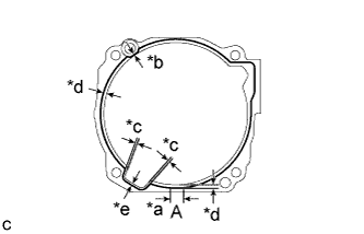
Text in Illustration *a 20 mm (0.787 in.) *b 1.0 mm (0.0394 in.) *c 1.4 mm (0.0551 in.) *d 3.0 mm (0.118 in.) *d 2.0 mm (0.0787 in.) Apply seal packing to the areas indicated in the illustration of the rear differential carrier assembly.
Seal packing Toyota Genuine Seal Packing 1281, Three Bond 1281 or equivalent Note
-
Start applying seal packing within range (A).
-
Make sure that the clearance from the center of the bead is within 1 mm (0.0394 in.).
-
Apply seal packing in a continuous bead 2 to 3 mm (0.0787 to 0.118 in.) in diameter.
-
If there is an area where seal packing is not applied in a continuous bead, be sure to apply seal packing by overlapping the ends of the bead at least 10 mm (0.394 in.).
-
Stop applying seal packing after allowing it to overlap with the beginning of the bead by at least 10 mm (0.394 in.) within range (A) in the illustration.
-
Install the electro magnetic control coupling sub-assembly within 10 minutes after applying seal packing. If the electro magnetic control coupling sub-assembly is not installed within 10 minutes after applying seal packing, completely remove and then reapply seal packing.
-
After installing the electro magnetic control coupling sub-assembly, do not immediately add oil or drive the vehicle for at least 1 hour.
-
-
Install the electro magnetic control coupling sub-assembly with the 4 bolts.
- Torque:
- 20 N*m { 200 kgf*cm, 14 ft.*lbf }
Note
-
Do not damage the diaphragm oil seal.
-
Do not damage the contact surface of the rear differential carrier assembly and electro magnetic control coupling sub-assembly.
-
Connect the electro magnetic control coupling sub-assembly connector and vacuum hose.
Note
Do not damage the electro magnetic control coupling wire harness.
-
-
ADD DIFFERENTIAL OIL
-
Remove the rear differential carrier cover plug.
-
Add differential oil Click here.
-
-
INSPECT DIFFERENTIAL OIL
-
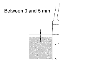
Check that the oil level is between 0 and 5 mm (0 and 0.196 in.) from the bottom lip of the rear differential carrier cover plug opening.
-
Inspect for oil leaks if the oil level is low.
-
-
INSTALL REAR DIFFERENTIAL CARRIER COVER PLUG
-
Using a 10 mm hexagon wrench, install a new gasket and the rear differential carrier cover plug.
- Torque:
- 39 N*m { 398 kgf*cm, 29 ft.*lbf }
-
-
INSPECT FOR DIFFERENTIAL OIL LEAK
-
TEMPORARILY TIGHTEN PROPELLER WITH CENTER BEARING SHAFT ASSEMBLY
-
Remove SST from the transfer.
- SST
- 09325-20010
-
Install the propeller with center bearing shaft assembly.
Note
-
Be careful not to damage the oil seal.
-
Be careful not to damage the universal joint boot when installing the propeller shaft.
-
-
Text in Illustration *1 Matchmark Align the matchmarks on the rear propeller shaft and electromagnetic control coupling assembly and install the 4 nuts and 4 washers temporarily.
Note
Do not allow grease to adhere to be bolts or washers.
-
Temporarily install the propeller with center bearing shaft assembly with the 4 bolts, 2 No. 1 center support bearing washers and 2 No. 2 center support bearing washers.
Note
-
Reuse the washers.
-
Do not allow grease to adhere to be bolts or washers.
-
-
Fully tighten the 4 nuts.
- Torque:
- 37 N*m { 379 kgf*cm, 27 ft.*lbf }
-
-
FULLY TIGHTEN PROPELLER WITH CENTER BEARING SHAFT ASSEMBLY
- SST
- 09370-50010
-
Remove the piece of cloth or equivalent from the universal joint.
-
Depress the brake pedal and hold it.
-
Using a hexagon wrench (6 mm), tighten the 6 bolts.
- Torque:
- 26 N*m { 265 kgf*cm, 19 ft.*lbf }
-
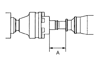
With the vehicle unloaded, adjust the dimension between the rear side of the cover and shaft as shown in the illustration.
Length A 65.5 to 70.5 mm (2.579 to 2.776 in.) -
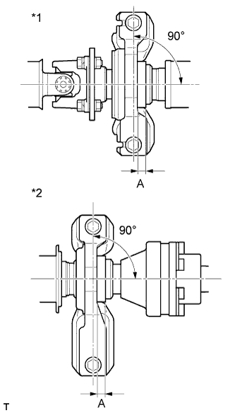
Text in Illustration *1 No. 1 Center Support Bearing Assembly *2 No. 2 Center Support Bearing Assembly With the vehicle unloaded, adjust the front and rear dimensions between the edge surface of the center support bearing and the edge surface of the cushion respectively as shown in the illustration, and then tighten the bolts.
Length A 11.5 to 13.5 mm (0.453 to 0.532 in.) -
Check that the center line of the bracket is at a right angle to the shaft axial direction.
-
Fully tighten the 4 bolts.
- Torque:
- 37 N*m { 375 kgf*cm, 27 ft.*lbf }
-
INSTALL CENTER EXHAUST PIPE ASSEMBLY
-
Install the center exhaust pipe assembly Click here.
-
-
INSPECT AND ADJUST TRANSFER OIL
-
Inspect and adjust transfer oil Click here.
-
-
INSPECT FOR TRANSFER OIL LEAK