REAR AXLE HUB (for AWD) INSTALLATION

Tech Tips
-
Use the same procedure for the RH side and LH side.
-
The procedure listed below is for the LH side.
-
INSTALL REAR AXLE HUB AND BEARING ASSEMBLY
-
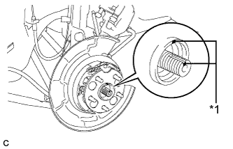
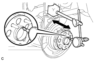
Text in Illustration *1 Matchmark Align the matchmarks on the rear drive shaft assembly and the rear axle hub and bearing assembly.
Note
Do not rotate the rear drive shaft.
-
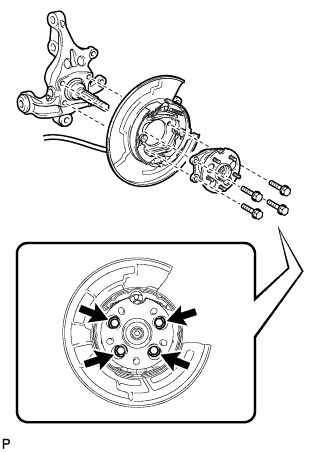
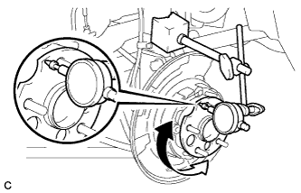
Install the parking brake assembly and the rear axle hub and bearing assembly with the 4 bolts.
- Torque:
- 80 N*m { 816 kgf*cm, 59 ft.*lbf }
Note
Do not twist the parking brake cable assembly when installing it.
-
-
INSTALL REAR AXLE SHAFT NUT
-
Clean the threaded parts on the rear drive shaft assembly and a new rear axle shaft nut using a non-residue solvent.
Note
-
Be sure to perform this work for a new rear drive shaft assembly.
-
Keep the threaded parts free of oil and foreign matter.
-
-
install the rear disc with the 5 hub nuts.
-
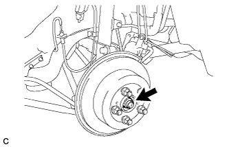
While applying the parking brakes, temporarily install the new rear axle shaft nut.
- Torque:
- 294 N*m { 2998 kgf*cm, 217 ft.*lbf }
Note
Stake the nut after inspecting for looseness and runout in the following steps.
-
Remove the 5 hub nuts and the rear disc.
-
-
INSTALL REAR SPEED SENSOR
-
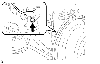
Install the rear speed sensor to the rear axle carrier sub-assembly with the bolt.
- Torque:
- 8.5 N*m { 87 kgf*cm, 75 in.*lbf }
Note
-
Keep the rear speed sensor tip and sensor installation hole free of foreign matter.
-
Do not twist the rear speed sensor wire when installing it.
-
-
INSPECT REAR AXLE HUB BEARING LOOSENESS
-
Using a dial indicator, check for looseness near the center of the rear axle hub and bearing assembly.
Maximum looseness 0.05 mm (0.00196 in.) Note
Ensure that the dial indicator is set perpendicular to the measurement surface.
If the looseness exceeds the maximum, replace the rear axle hub and bearing assembly.
-
-
INSPECT REAR AXLE HUB RUNOUT
-
Using a dial indicator, check for runout on the surface of the rear axle hub and bearing assembly outside the rear axle hub bolt.
Maximum runout 0.08 mm (0.00314 in.) Note
Ensure that the dial indicator is set perpendicular to the measurement surface.
If the runout exceeds the maximum, replace the rear axle hub and bearing assembly.
-
-
INSTALL REAR DISC
-
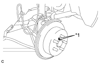
Text in Illustration *1 Matchmark Align the matchmarks of the rear disc and axle hub, and install the rear disc.
Note
When installing a new rear disc, select the installation position where the rear disc has minimal runout.
-
-
INSTALL REAR DISC BRAKE CALIPER ASSEMBLY
-
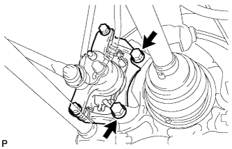
Install the rear disc brake caliper assembly with the 2 bolts.
- Torque:
- 78 N*m { 800 kgf*cm, 58 ft.*lbf }
-
-
STAKE REAR AXLE SHAFT NUT
-
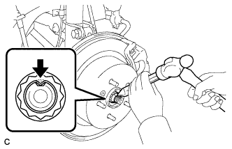
Using a chisel and a hammer, stake the rear axle shaft nut.
-
-
INSTALL REAR WHEEL
- Torque:
- 103 N*m { 1050 kgf*cm, 76 ft.*lbf }
-
CHECK FOR SPEED SENSOR SIGNAL
-
Check for the speed sensor signal Click here.
-