STEERING KNUCKLE INSTALLATION

Tech Tips
-
Use the same procedure for the RH side and LH side.
-
The procedure listed below is for the LH side.
-
INSTALL STEERING KNUCKLE
-

Using SST and a press, install a new front axle hub bearing to the steering knuckle.
- SST
- 09950-60020 ( 09951-00810 )
- 09950-70010 ( 09951-07100 )
-
-
INSTALL FRONT DISC BRAKE DUST COVER
-
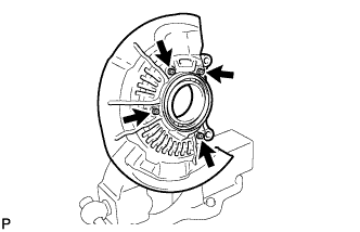
Install the front disc brake dust cover to the steering knuckle with the 4 bolts.
- Torque:
- 8.3 N*m { 85 kgf*cm, 73 in.*lbf }
-
-
INSTALL FRONT AXLE HUB SUB-ASSEMBLY
-
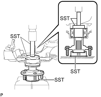
Using SST and a press, install the front axle hub sub-assembly to the steering knuckle.
- SST
- 09608-32010
- 09950-60010 ( 09951-00620 )
- 09950-70010 ( 09951-07100 )
-
-
INSTALL FRONT AXLE HUB HOLE SNAP RING
-
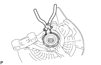
Using snap ring pliers, install a new front axle hub hole snap ring.
-
-
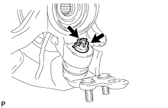
INSTALL FRONT NO. 1 WHEEL BEARING DUST DEFLECTOR
-
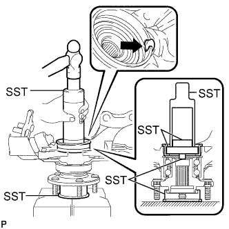
Using SST and a hammer, install a new front No. 1 wheel bearing dust deflector.
- SST
- 09316-60011 ( 09316-00011 )
- 09608-32010
- 09950-60010 ( 09951-00500 )
- 09950-60020 ( 09951-00810, 09952-06010 )
Tech Tips
Align the cutout for the speed sensor in the No. 1 front wheel bearing dust deflector with the hole of the steering knuckle.
-
-
INSTALL FRONT LOWER BALL JOINT
-
Install the front lower ball joint to the steering knuckle with the nut.
- Torque:
- 123 N*m { 1254 kgf*cm, 91 ft.*lbf }
Note
Prevent oil from adhering to the screw and tapered parts.
-
Install a new cotter pin.
Note
If the holes for the cotter pin are not aligned, tighten the nut further up to 60°.
-
-
INSTALL FRONT AXLE ASSEMBLY
Tech Tips
Refer to the procedures from "Install Front Axle Assembly" Click here.