REAR DRIVE SHAFT ASSEMBLY (for AWD) INSTALLATION

-
INSTALL REAR DRIVE SHAFT ASSEMBLY
-
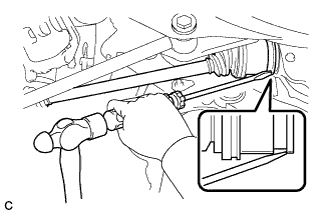
Align the shaft splines and install the rear drive shaft assembly using a screwdriver and hammer.
Note
-
Set the snap ring with the opening facing downward.
-
Be careful not to damage the oil seal, boot or dust cover.
-
Install the drive shaft assembly while keeping it level.
-
-
-
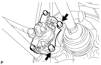
INSTALL REAR AXLE CARRIER SUB-ASSEMBLY
-
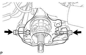
Temporarily install the rear axle carrier sub-assembly with the 2 bolts and 2 nuts.
Note
-
Be careful not to damage the outboard joint boot.
-
Be careful not to damage the speed sensor rotor.
-
Keep the speed sensor rotor free of foreign matter.
-
-
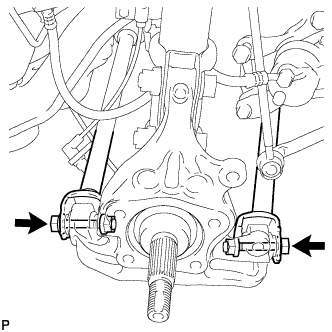
Install the rear axle carrier sub-assembly with the 2 bolts and 2 nuts.
- Torque:
- 290 N*m { 2957 kgf*cm, 214 ft.*lbf }
Note
-
Be careful not to damage the outboard joint boot.
-
Be careful not to damage the speed sensor rotor.
-
Keep the speed sensor rotor free of foreign matter.
-
Do not rotate the drive shaft with the rear axle hub and bearing assembly removed.
-
When installing the nuts, keep the bolts from rotating.
Tech Tips
Insert the bolts from the rear side.
-
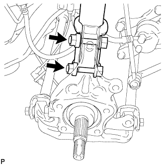
Fully tighten the rear No. 2 suspension arm assembly and the rear No. 1 suspension arm assembly with the 2 bolts and 2 nuts.
- Torque:
- 112 N*m { 1141 kgf*cm, 82 ft.*lbf }
Note
Since stopper nuts are used, tighten the bolts.
-
-
INSPECT REAR STRUT ROD ASSEMBLY
-

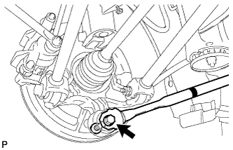
Text in Illustration *1 Identification Mark Temporarily install the rear strut rod assembly to the rear axle carrier sub-assembly with the bolt and the nut.
Note
-
Ensure that the identification mark faces the inside of the vehicle.
-
Since a stopper nut is used, temporarily tighten the bolt.
-
-
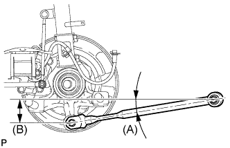
Set the rear strut rod assembly in the tightening position shown in the illustration.
Standard angle (A) 9°3' (9.04°) Standard length (B) 78.3 mm (3.08 in.) -
Fully tighten the bolt in the tightening position.
- Torque:
- 80 N*m { 816 kgf*cm, 59 ft.*lbf }
-
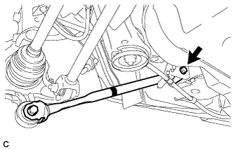
Temporarily install the rear strut rod assembly to the body with the bolt and the nut.
-
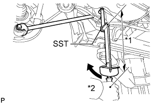
Text in Illustration *1 Fulcrum Length *2 Turn Using SST and a socket wrench (17 mm), fully tighten the bolt in the rebound position.
- SST
- 09961-00950
- Torque:
- without SST
- 80 N*m { 816 kgf*cm, 59 ft.*lbf }
- with SST
- 59 N*m { 603 kgf*cm, 44 ft.*lbf }
Note
-
Since a stopper nut is used, fully tighten the bolt.
-
Use a torque wrench with a fulcrum length of 425 mm (1.39 ft.).
-
This torque value is effective when SST is parallel to the torque wrench.
-
-
INSTALL NO. 3 PARKING BRAKE CABLE ASSEMBLY
-
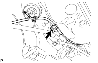
Install the No. 3 parking brake cable assembly with the bolt.
- Torque:
- 6.0 N*m { 61 kgf*cm, 53 in.*lbf }
Note
Do not twist the No. 3 parking brake cable assembly when installing it.
-
-
INSTALL REAR AXLE HUB AND BEARING ASSEMBLY
-
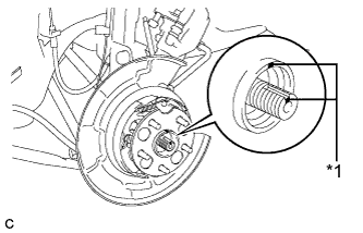
Text in Illustration *1 Matchmark Align the matchmarks on the rear drive shaft assembly and the rear axle hub and bearing assembly.
Note
Do not rotate the rear drive shaft.
-
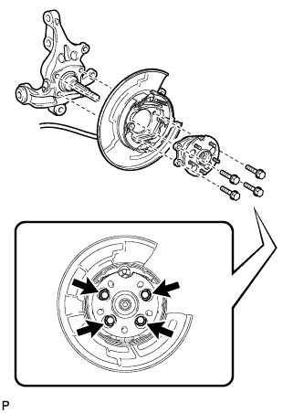
Install the parking brake assembly and the rear axle hub and bearing assembly with the 4 bolts.
- Torque:
- 80 N*m { 816 kgf*cm, 59 ft.*lbf }
Note
Do not twist the parking brake cable assembly when installing it.
-
-
INSTALL REAR SPEED SENSOR
-
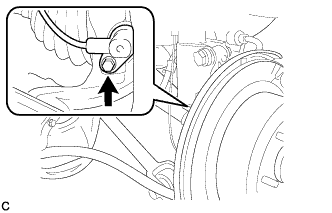
Install the rear speed sensor to the rear axle carrier sub-assembly with the bolt.
- Torque:
- 8.5 N*m { 87 kgf*cm, 75 in.*lbf }
Note
-
Keep the rear speed sensor tip and sensor installation hole free of foreign matter.
-
Do not twist the rear speed sensor wire when installing it.
-
-
INSTALL REAR DISC
-
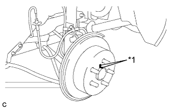
Text in Illustration *1 Matchmark Align the matchmarks of the rear disc and axle hub, and install the rear disc.
Note
When installing a new rear disc, select the installation position where the rear disc has minimal runout.
-
-
INSTALL REAR DISC BRAKE CALIPER ASSEMBLY
-
Install the rear disc brake caliper assembly with the 2 bolts.
- Torque:
- 78 N*m { 800 kgf*cm, 58 ft.*lbf }
-
-
INSTALL REAR AXLE SHAFT NUT
-
Clean the threaded parts on the drive shaft and axle shaft nut using a non-residue solvent.
Note
-
Be sure to perform this work for a new drive shaft.
-
Keep the threaded parts free of oil and foreign objects.
-
-
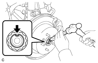
Install a new rear axle shaft nut.
- Torque:
- 294 N*m { 2998 kgf*cm, 217 ft.*lbf }
-
Using a chisel and hammer, stake the rear axle shaft nut.
-
-
INSTALL REAR WHEEL
- Torque:
- 103 N*m { 1050 kgf*cm, 76 ft.*lbf }
-
STABILIZE SUSPENSION
-
Lower the vehicle to the ground.
-
Bounce the vehicle up and down at the corners to stabilize the rear suspension.
-
-
INSPECT DIFFERENTIAL OIL
-
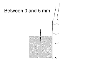
Check that the oil level is between 0 and 5 mm (0 and 0.196 in.) from the bottom lip of the rear differential carrier cover plug opening.
-
Inspect for oil leaks if the oil level is low.
-
-
INSPECT AND ADJUST REAR WHEEL ALIGNMENT
Tech Tips
-
CHECK ABS SPEED SENSOR SIGNAL
Tech Tips